
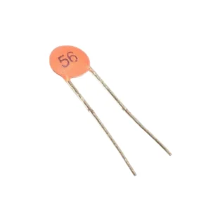
The 103 Ceramic Capacitor is a compact non-polar ceramic capacitor with a capacitance value of 10,000pF (10nF or 0.01μF). It is widely used in electronic circuits for filtering, noise suppression, signal coupling, timing circuits, oscillators, RF applications, and general-purpose circuit design.
The capacitor features a non-polarized design, allowing it to be connected in either direction, making installation simple and convenient for both prototyping and production applications.
Key Features of 103 Ceramic Capacitor
- Capacitance Value: 10,000pF (10nF / 0.01μF)
- Marking Code: 103
- Non-Polar Design: Can be connected in any orientation
- Stable Ceramic Dielectric: Reliable performance across a wide range of applications
- Compact Through-Hole Package: Easy PCB mounting and breadboard use
- Low Leakage Current: Suitable for signal and timing circuits
- High Reliability: Long operational lifespan
- Ideal for High-Frequency Applications: Commonly used in RF and oscillator circuits
- Wide Voltage Rating Options: Available in various voltage specifications
- Excellent Temperature Stability: Consistent performance across temperature ranges
Technical Specifications
- Product Type: Ceramic Capacitor
- Capacitance: 10,000pF
- Capacitance in nF: 10nF
- Capacitance in μF: 0.01μF
- Capacitor Code: 103
- Polarity: Non-Polarized
- Mounting Type: Through-Hole
- Dielectric Type: Ceramic
- Tolerance: Typically ±5% to ±20% (varies by manufacturer)
- Rated Voltage: Varies depending on model and manufacturer
- Lead Type: Radial Leads
- Operating Temperature: Depends on capacitor series
- Lead Spacing: Standard pitch for easy installation
Understanding the 103 Capacitor Code
The marking 103 follows the standard capacitor coding system used worldwide for ceramic capacitors. This three-digit code provides a quick and easy way to identify the capacitance value.
How to Read the 103 Code
- First two digits: 10 (significant figures)
- Third digit: 3 (number of zeros to add)
- Result is always in picofarads (pF)
Calculation Method
10 × 10³ = 10,000pF
Equivalent Capacitance Values
- 10,000pF (picofarads)
- 10nF (nanofarads)
- 0.01μF (microfarads)
Working Principle of Ceramic Capacitors
A ceramic capacitor stores electrical energy in an electric field between two conductive plates separated by a ceramic dielectric material. The ceramic dielectric provides excellent insulation properties and stable capacitance across various operating conditions.
Primary Functions in Electronic Circuits
- Filter unwanted electrical noise and interference
- Stabilize voltage levels in power supply circuits
- Pass AC signals while blocking DC components
- Improve circuit performance in high-frequency applications
- Provide decoupling between circuit stages
- Create timing circuits when combined with resistors
- Tune resonant frequencies in oscillator circuits
Applications of 10nF Ceramic Capacitor
Microcontroller and Digital Applications
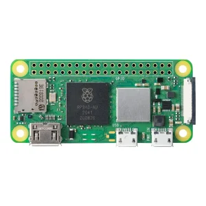
- Arduino and Raspberry Pi projects
- Microcontroller power supply decoupling
- Digital signal processing circuits
- Reset circuit timing
- Crystal oscillator circuits
Analog and RF Applications
- RF circuits and impedance matching
- Oscillator and resonator circuits
- Signal coupling and decoupling
- Audio circuits and tone control
- Communication equipment
- Antenna tuning circuits
Power and Filtering Applications
- Power supply filtering and smoothing
- Noise suppression and EMI filtering
- Bypass capacitor applications
- Voltage regulator circuits
- Switch mode power supply filtering
General Electronics Applications
- Educational electronics projects
- Hobbyist circuit designs
- Prototyping and development boards
- Consumer electronics repair
- DIY electronics kits
Advantages of Non-Polar Ceramic Capacitors
- Non-polarized for easy installation in any direction
- Compact and lightweight design saves PCB space
- Low cost and highly reliable for mass production
- Suitable for high-frequency operation up to GHz range
- Long service life with minimal degradation
- Stable electrical characteristics over time
- Wide operating temperature range
- Excellent frequency response characteristics
- Low Equivalent Series Resistance (ESR)
- Self-healing properties in some ceramic types
Installation and Usage Guidelines
Before Installation
- Verify the capacitance value using the 103 marking code
- Check the voltage rating matches your circuit requirements
- Ensure the capacitor is free from physical damage
- Identify the correct placement on your PCB or breadboard
During Installation
- Keep leads as short as possible in high-frequency circuits to minimize parasitic inductance
- Mount close to the IC or component it is protecting
- Ensure proper spacing from heat-generating components
- Use appropriate soldering temperature and duration
- Verify orientation is correct for your circuit (though polarity does not matter)
Best Practices for Optimal Performance
- Use within the capacitor’s rated voltage range
- Store in a dry environment to maintain reliability
- Suitable for both breadboard prototyping and PCB designs
- Consider tolerance when precision is required
- Test the circuit after installation to verify proper operation
- Keep spare capacitors on hand for replacement and testing
Comparing Ceramic Capacitor Types
Class 1 vs Class 2 Ceramic Capacitors
Ceramic capacitors are divided into different classes based on their dielectric materials:
- Class 1 (C0G/NP0): High stability, low losses, temperature-stable, ideal for precision timing and resonant circuits
- Class 2 (X7R, Y5V): Higher capacitance in smaller size, moderate stability, suitable for coupling and decoupling applications
Why Choose the 103 10nF Ceramic Capacitor
The 10nF (0.01μF) capacitance value is one of the most commonly used values in electronics, making the 103 ceramic capacitor an essential component for any electronics toolkit or production inventory. Its versatility, reliability, and cost-effectiveness make it ideal for both hobbyists and professional engineers.
Whether you are building Arduino projects, designing RF circuits, or creating power supply filters, the 103 ceramic capacitor provides dependable performance across a wide range of applications.
Note: Images are for illustration purposes only.


Reviews
There are no reviews yet