
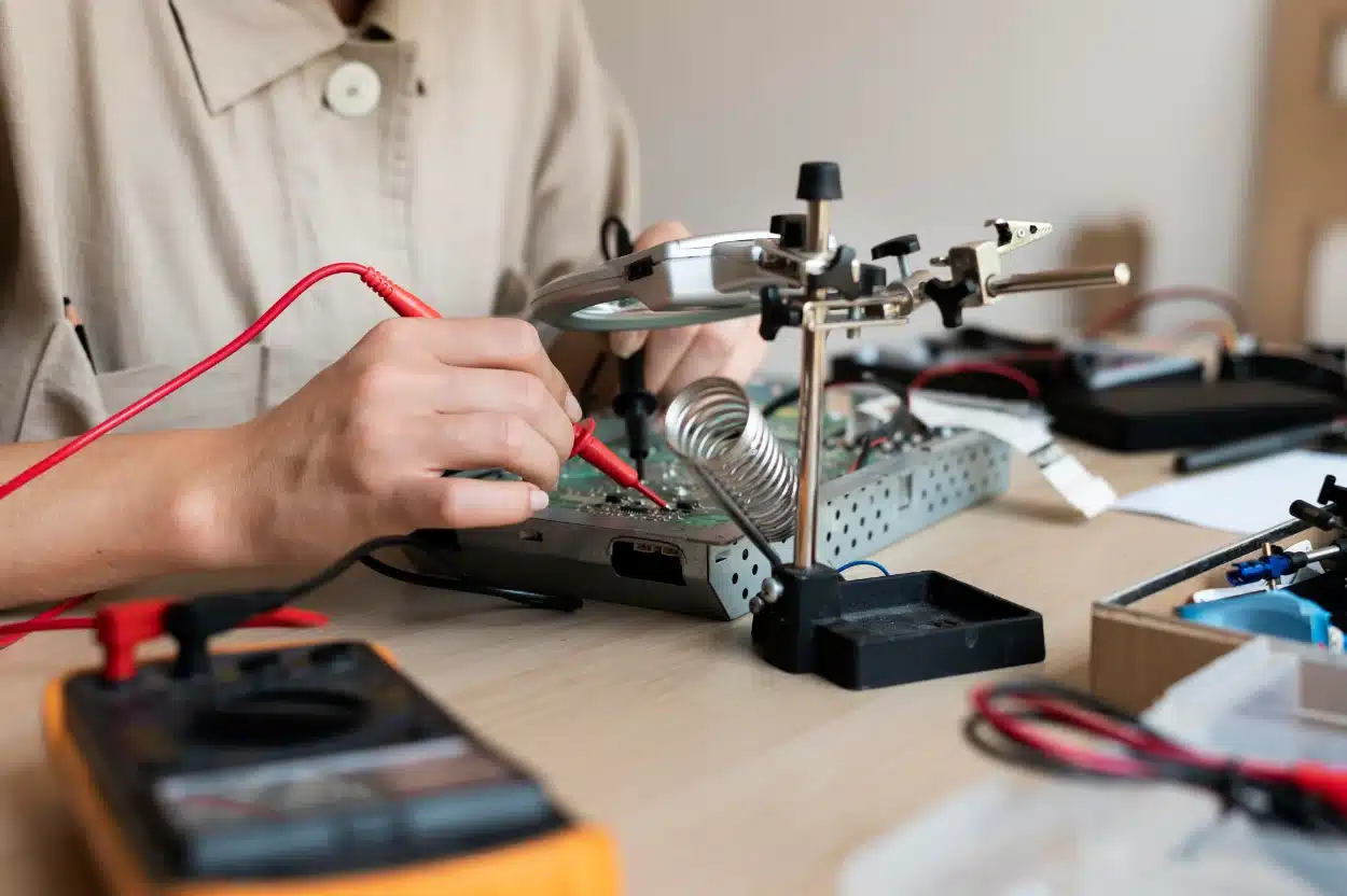
You have a project to submit, a science exhibition coming up, or you simply want to understand how circuits work. These ten basic electronics projects take you from your first glowing LED to a working Arduino traffic light. Each one lists the parts, how to build it and what it teaches, and every part is one we stock at College Road Electronics in Rawalpindi.
Quick answer: the best electronic projects for students start small. Build an LED with a resistor on a breadboard first, then a 5V supply, a buzzer, a light-sensing night lamp and a 555 flasher. Once those work, move to counters and an Arduino. All ten projects below run on batteries, so they are safe for school students.
Which project suits which class?
| Class | Projects | What it teaches |
|---|---|---|
| Class 6 to 8 | 1. LED with a resistor; 3. Push-button buzzer; 4. Automatic night lamp | Current, polarity, switches, sensors |
| Class 8 to 9 | 2. 5V supply from a 9V battery; 5. Touch switch; 6. Water level indicator | Voltage regulation, transistors as switches |
| Class 9 to 10, O Level, FSc | 7. 555 LED flasher; 9. Digital counter; 10. IR remote tester | Timers, ICs, digital logic, signals |
| Class 10, O Level, first-year college | 8. Arduino traffic light | Microcontrollers and simple code |
What you need before you start
Every project here is built on a breadboard first, so nothing is soldered until it works. You need a way to connect parts, a way to power them and a way to measure.
| Item | Why you need it | Price |
|---|---|---|
| MB102 830 Tie Points Solderless Breadboard | Push parts in and out without soldering | Rs 240 |
| 20cm Male-to-Male Jumper Wires | Connect rows on the breadboard | Rs 80 |
| Power Plus 9V Alkaline Battery and 9V Battery Clip Connector | A safe power source for every project | Rs 150 and Rs 30 |
| DT830D Digital Pocket Size Multimeter | Check voltages, resistor values and broken wires | Rs 750 |
| Metal Film Resistors (1Ω – 820Ω) and Metal Film Resistors (1kΩ – 10MΩ) | Limit current and set voltages | Rs 2 each |
| 5mm LEDs in red, green, yellow, blue and white | The easiest way to see a circuit working | Rs 5 each |
Buy a few spare LEDs and resistors. Every student burns out at least one LED while learning, and that is how you learn why the resistor matters.
Project 1: LED with a resistor
Parts: one 5mm LED, one 330Ω to 470Ω resistor from the 1Ω – 820Ω pack, the 9V battery and clip, breadboard and jumper wires.
- Push the LED into the breadboard. The longer leg is the anode (positive).
- Connect the resistor from the anode to the positive rail.
- Connect the shorter leg (cathode) to the negative rail.
- Clip the battery to the rails. The LED should light.
What it teaches: the resistor limits the current. Without it, the LED takes too much current from a 9V battery and burns out. If the LED stays dark, turn it round: it only conducts one way. The same idea lights the indicator LED on every charger and remote control.
Project 2: A 5V supply from a 9V battery
Many parts, including buzzers, ICs and the IR receiver in project 10, want 5V, not 9V. This project gives you a steady 5V for the rest of the list.
Parts: L7805 7805 Positive Voltage Regulator IC (Rs 25), a 10μF 50V Electrolytic Capacitor (Rs 15), a 104 0.1μF Ceramic Capacitor (Rs 5), an LED with a 330Ω resistor, and the 9V battery.
- Hold the 7805 with its writing facing you: the pins are input, ground and output from left to right.
- Battery positive goes to input, battery negative to ground.
- Put the 10μF capacitor between input and ground (its stripe, the negative side, to ground) and the 0.1μF capacitor between output and ground.
- Connect the LED and resistor to the output as a power indicator, and measure the output with the multimeter. It should read close to 5V.
What it teaches: a regulator holds its output steady while the battery voltage drops. Mobile chargers and Arduino boards use the same principle.
Project 3: Push-button buzzer (doorbell)
Parts: Electromagnetic Active Buzzer 5V (Rs 40), a Tactile Push Button Switch (from Rs 5), and the 5V supply from project 2.
Connect the button and the buzzer in series across the 5V supply, with the buzzer’s longer leg (positive) towards 5V. Press the button and the buzzer sounds; release it and it stops.
What it teaches: a switch completes or breaks a circuit. An active buzzer has its own oscillator inside, so it only needs power. Doorbells and simple alarms work this way.
Project 4: Automatic night lamp with an LDR
Parts: LDR Light Dependent Resistor (GL5506 5mm) (Rs 15), a BC547 NPN Transistor (Rs 7), a 10kΩ resistor, a 330Ω resistor, an LED, and the 9V battery. Add a trimpot (Rs 30) if you want to adjust when the lamp turns on.
- Connect the 10kΩ resistor (or the trimpot) from positive to the transistor’s base.
- Connect the LDR from the base to negative.
- Connect the LED and 330Ω resistor from positive to the collector, and the emitter to negative.
- Cover the LDR with your hand. The LED turns on.
What it teaches: an LDR’s resistance rises in the dark. That raises the voltage at the base, the transistor switches on and the LED lights. Automatic street lights use the same idea.
Project 5: Touch switch with two transistors
Parts: two BC547 NPN Transistors (Rs 7 each), a 330Ω resistor, an LED, two short bare wires as touch plates, and the 9V battery.
Connect the two transistors as a Darlington pair: the first transistor’s emitter goes to the second transistor’s base, and both collectors join. Put the LED and resistor between positive and the joined collectors, and the second emitter to negative. One touch wire goes to positive, the other to the first transistor’s base. Touch both wires with one finger and the LED lights.
What it teaches: your skin passes a tiny current, too small to light an LED. Two transistors amplify it enough to switch the LED on. Touch lamps work on this principle.
Project 6: Water level indicator
Parts: three BC547 transistors, three LEDs (green, yellow, red), three 330Ω resistors, three 1kΩ resistors, Hard Core Wire for Breadboard (Rs 50 per metre) for the probes, a glass of water and the 9V battery.
- Build one transistor stage per level: LED and 330Ω resistor from positive to the collector, emitter to negative, and a 1kΩ resistor from the base to a probe wire.
- Put a common probe connected to positive at the bottom of the glass.
- Fix the three level probes at low, middle and high points.
- Pour in water. Each LED lights as the water reaches its probe.
What it teaches: tap water conducts a little, enough to switch a transistor. Add the 5V buzzer from project 3 to the top level and you have an overflow alarm for a water tank, a favourite exhibition model. For an Arduino version, use the Water Level Sensor Module (Rs 100).
Project 7: 555 timer LED flasher
Parts: 555 Timer IC NE555 (Rs 15), a 10μF 50V capacitor (Rs 15), a 1kΩ and a 47kΩ resistor, an LED with a 330Ω resistor, and the 9V battery.
- Pins 8 and 4 go to positive, pin 1 to negative.
- The 1kΩ resistor goes from pin 7 to positive, the 47kΩ resistor from pin 7 to pin 6.
- Join pins 6 and 2, and put the 10μF capacitor from pin 2 to negative.
- The LED and 330Ω resistor go from pin 3 (output) to negative. The LED blinks a little faster than once a second.
What it teaches: the 555 charges and discharges the capacitor through the resistors, switching its output on and off. Change the 47kΩ resistor or the capacitor and the speed changes. A larger capacitor gives a slower blink.
Project 8: Traffic light with an Arduino
Parts: Arduino Uno R3 SMD Development Board (Rs 900) or the Arduino Uno R3 DIP (Rs 1,150), an Arduino UNO and MEGA USB Cable (Rs 110), red, yellow and green LEDs, three 330Ω resistors, breadboard and jumper wires.
- Connect each LED through its resistor to pins 8 (red), 9 (yellow) and 10 (green), and the cathodes to GND.
- In the Arduino IDE, set the three pins as outputs in
setup(). - In
loop(), turn on red, wait 5 seconds; turn on green, wait 5 seconds; turn on yellow, wait 2 seconds. UsedigitalWrite()anddelay(). - Upload the sketch over USB. The Arduino powers itself from the computer.
What it teaches: a microcontroller replaces a whole circuit with a few lines of code. Change the timings and the lights change. This is the usual first step into robotics. Our guide to Arduino and ESP32 projects for students takes it further.
Project 9: Digital counter 0 to 9
Parts: CD4026 7-Segment Counter IC (Rs 70), a 1-Digit 7-Segment Common Cathode LED Display (Rs 35), seven 330Ω resistors, a push button with a 10kΩ resistor, and the 9V battery.
- Power the CD4026: pin 16 to positive, pin 8 to negative. Tie the reset (pin 15) and the clock inhibit (pin 2) to negative, and the display enable (pin 3) to positive.
- Connect the seven segment outputs (a to g) through the 330Ω resistors to the matching segments of the display, and the display’s common pin to negative.
- Connect the push button between positive and the clock input (pin 1), with the 10kΩ resistor from pin 1 to negative.
- Each press adds one to the number shown. For automatic counting, feed the clock from the 555 flasher in project 7.
What it teaches: a counter IC counts pulses and decodes them for the display itself. A push button often bounces and counts twice; that is a real-world problem worth explaining in your project report. Digital clocks and scoreboards build on this.
Project 10: IR remote tester
Parts: KY-022 IR Infrared Receiver Module 38kHz (Rs 100), an LED with a 1kΩ resistor, the 5V supply from project 2, and any TV remote.
Connect the module’s power and ground to the 5V supply. Connect the LED’s cathode to the module’s signal pin and its anode, through the 1kΩ resistor, to 5V. Point a remote at the module and press a button: the LED flickers as the signal arrives.
What it teaches: remotes send pulses of invisible infrared light at 38kHz, and the receiver turns them into electrical pulses. Repair shops use a tester like this to check whether a remote works. With an Arduino, the same module can read which button was pressed.
Want a ready-made exhibition model?
If the exhibition is close, a kit saves time and still lets you explain every part:
- DIY Fire Alarm Working Model Science Project (Rs 600): flame sensor, buzzer and LED.
- DIY Mini DC Water Pump Science Project Kit (Rs 500).
- More in Beginner STEM Kits and Intermediate Electronics Kits; for robotics, Advanced Robotics & Arduino Kits.
Moving a project from breadboard to a permanent board
Once a circuit works on the breadboard, you can solder it onto a Small Dotted Veroboard (Rs 100) so it survives the trip to school. A TU-2012A 40W Soldering Iron (Rs 800) and Solder Wire Volder 60/40 (Rs 200) are enough for these projects.
- Tin the iron’s tip with a little solder.
- Hold the iron on the joint for a second, feed in solder, remove the solder first, then the iron.
- A good joint is shiny and cone-shaped. A dull blob is a cold joint and will cause problems later.
- Wrap exposed wires with PVC insulating tape (Rs 140).
Work on a wooden board, keep the iron in its stand, and unplug it when you finish.
Why isn’t my circuit working?
| Problem | Likely cause | Fix |
|---|---|---|
| LED does not light | LED in backwards, or a flat battery | Turn the LED round; measure the battery with the multimeter |
| LED lit once, then died | No resistor, or a resistor too small | Always use 330Ω or more in series on 9V |
| Circuit works, then stops | Loose wire or cold solder joint | Press wires in firmly; re-solder dull joints |
| Resistor or IC gets hot | Wrong value or a short circuit | Disconnect, check the value and look for touching wires |
| Nothing works on the breadboard | The power rails are split in the middle | Many long breadboards break the rails halfway: bridge them with a jumper |
Why are there no mains-powered projects here?
Projects that use a 220V transformer or plug into the wall can give a dangerous shock if one wire is wrong. Every project in this guide runs on a 9V battery or USB power. If your syllabus asks for a mains power supply, build it only with your teacher, and test it with the multimeter before anyone touches it.
Frequently asked questions
What is the easiest electronic project for a student?
An LED with a resistor on a breadboard. It needs four parts, takes ten minutes and teaches polarity and current limiting, which every later project depends on.
Which electronic project is best for a science exhibition?
A water level indicator with an overflow buzzer, an automatic night lamp, or an Arduino traffic light. Judges like projects that solve a real problem and that you can explain part by part.
Do I need to know soldering to start?
No. Build everything on a breadboard first. Solder onto a veroboard only when the circuit works and you want it permanent.
Do I need an Arduino for these projects?
Only for project 8. The other nine use basic parts such as LEDs, resistors, transistors and the 555 and CD4026 ICs, which is the best way to learn how circuits work before you program them.
Where can I buy the parts in Pakistan?
Every part on this page is listed at College Road Electronics on College Road, Rawalpindi. We deliver nationwide across Pakistan at a flat rate of Rs 350, so you can order the full list for your project in one parcel.
