Sensor And Modules
Showing 1–15 of 200 results
-
Sensor And Modules, Students Corner
1 Channel Relay Module
- New 5V Relay Module
- can be used as a microcontroller development board module can be used as home appliance control
- 5 V-12V to the TTL control signal
- the control signal DC or AC, 220V AC load can be controlled.
- there is a normally open and one normally closed contact
- the power indicator light
- control indicator, pull off, disconnect does not shine
- transistor drive to increase the relay coil control pins high impedance.
- the control pin has a pull-down circuit to prevent malfunction relay vacant
SKU: n/a -
Sensor And Modules, Students Corner
125Khz reader Keychain
Product Specification
Packaging Type Box Frequency 125kHz Type Active RFID Usage/Application Access Control Installation Type Hand Held Material Abs SKU TTR-000063 Product Description
Description :
RC522 RFID Reader / Writer 13.56MHz with Cards Kit includes a 13.56MHz RF reader cum writer module that uses an RC522 IC and two S50 RFID cards. The MF RC522 is a highly integrated transmission module for contact-less communication at 13.56 MHz. RC522 supports ISO 14443A/MIFARE mode.
RC522 RFID Reader features an outstanding modulation and demodulation algorithm to serve effortless RF communication at 13.56 MHz. The S50 RFID Cards will ease up the process helping you to learn and add the 13.56 MHz RF transition to your project.
The module uses SPI to communicate with microcontrollers. The open-hardware community already has a lot of projects exploiting the RC522 RFID Communication, using Arduino.SKU: n/a -
Sensor And Modules, Students Corner
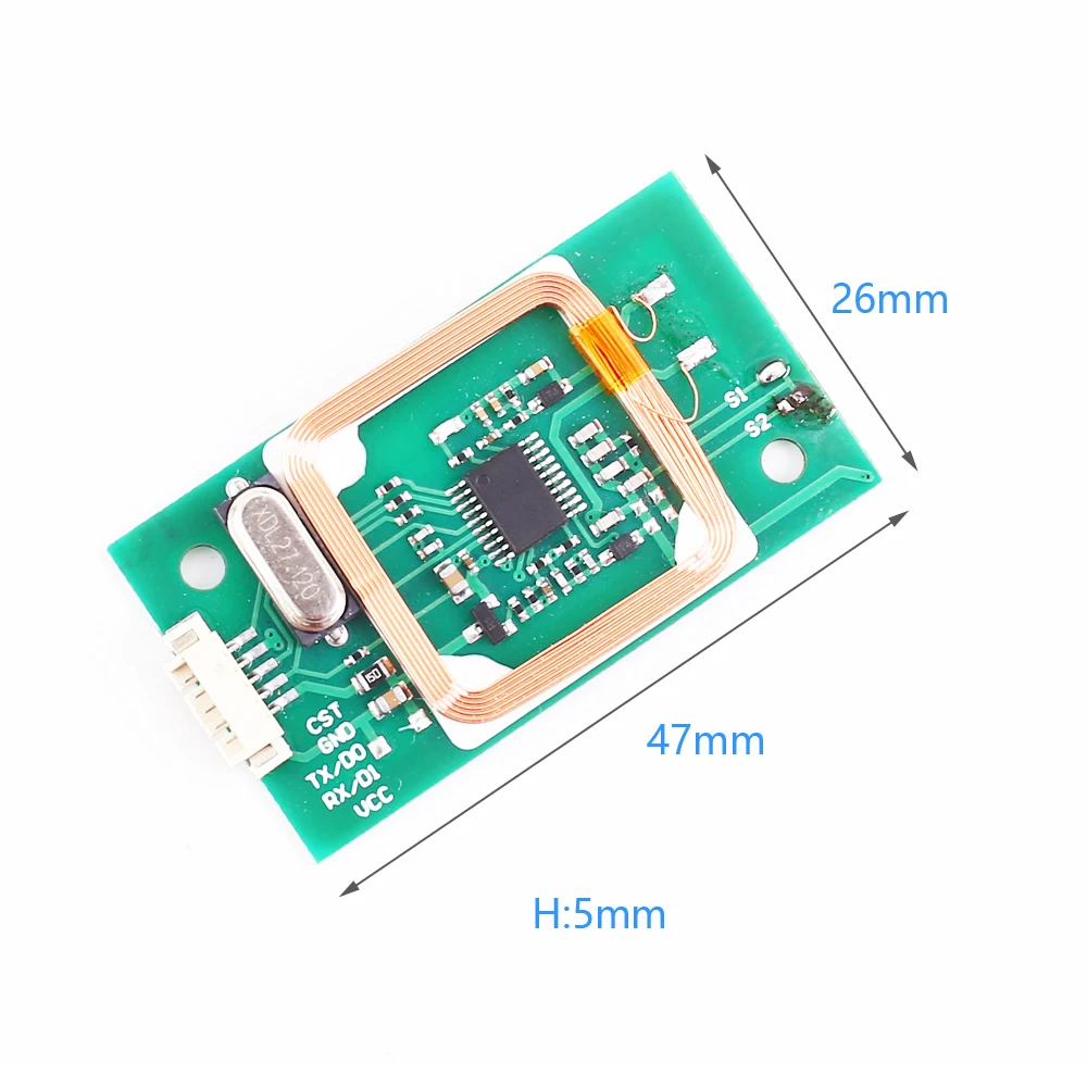
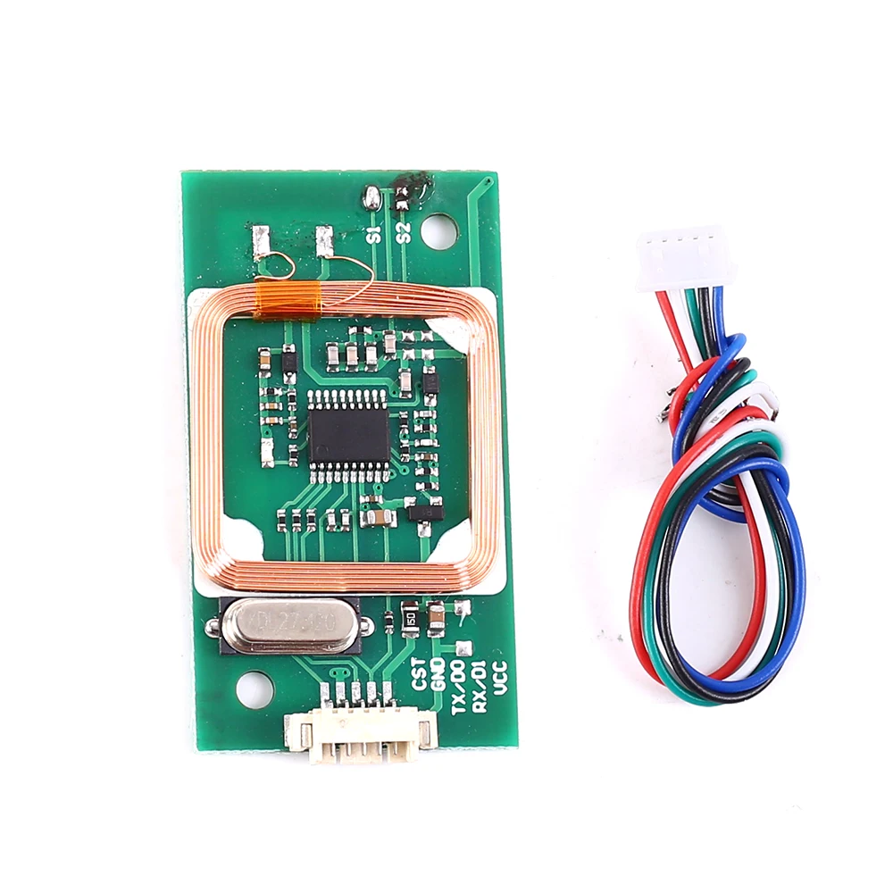
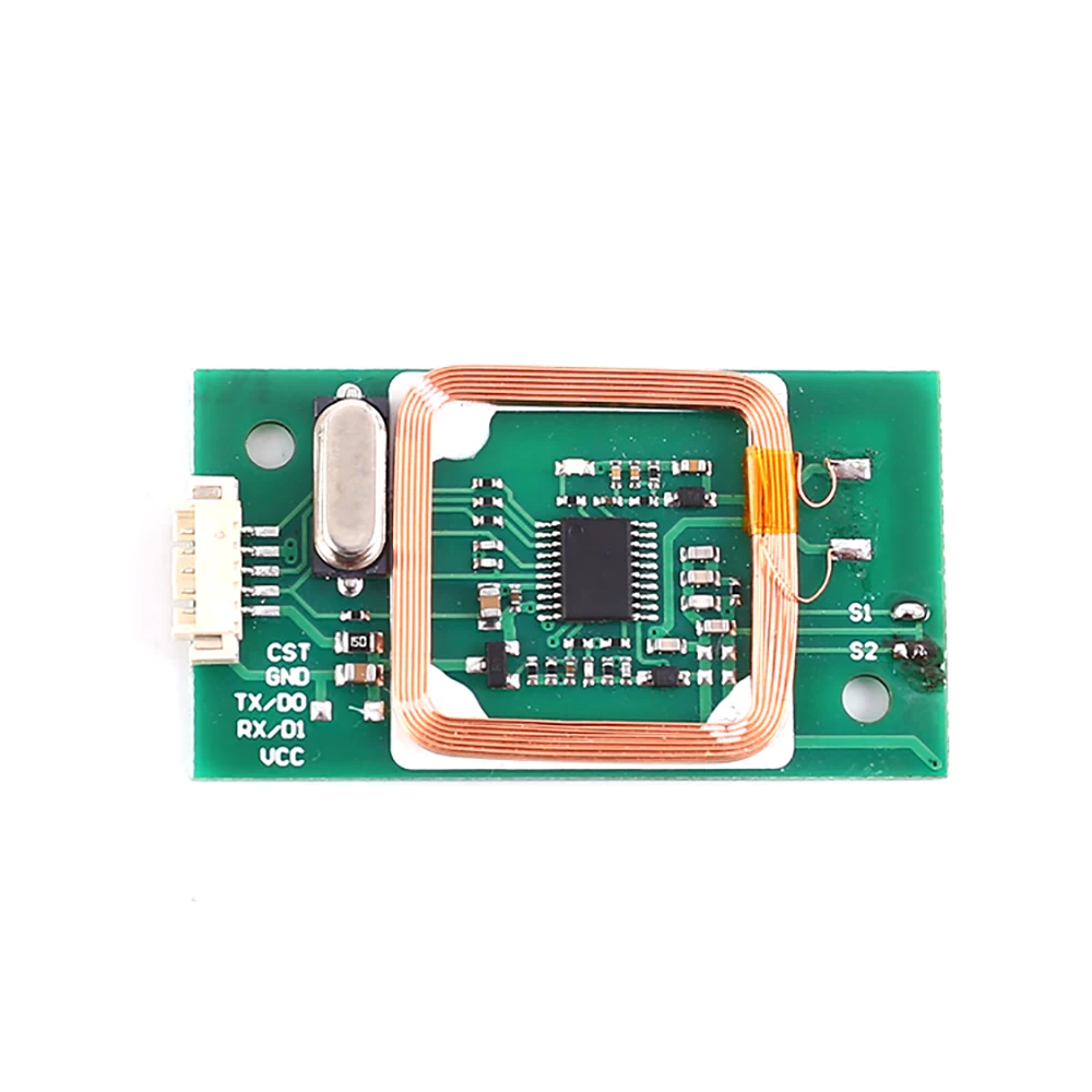
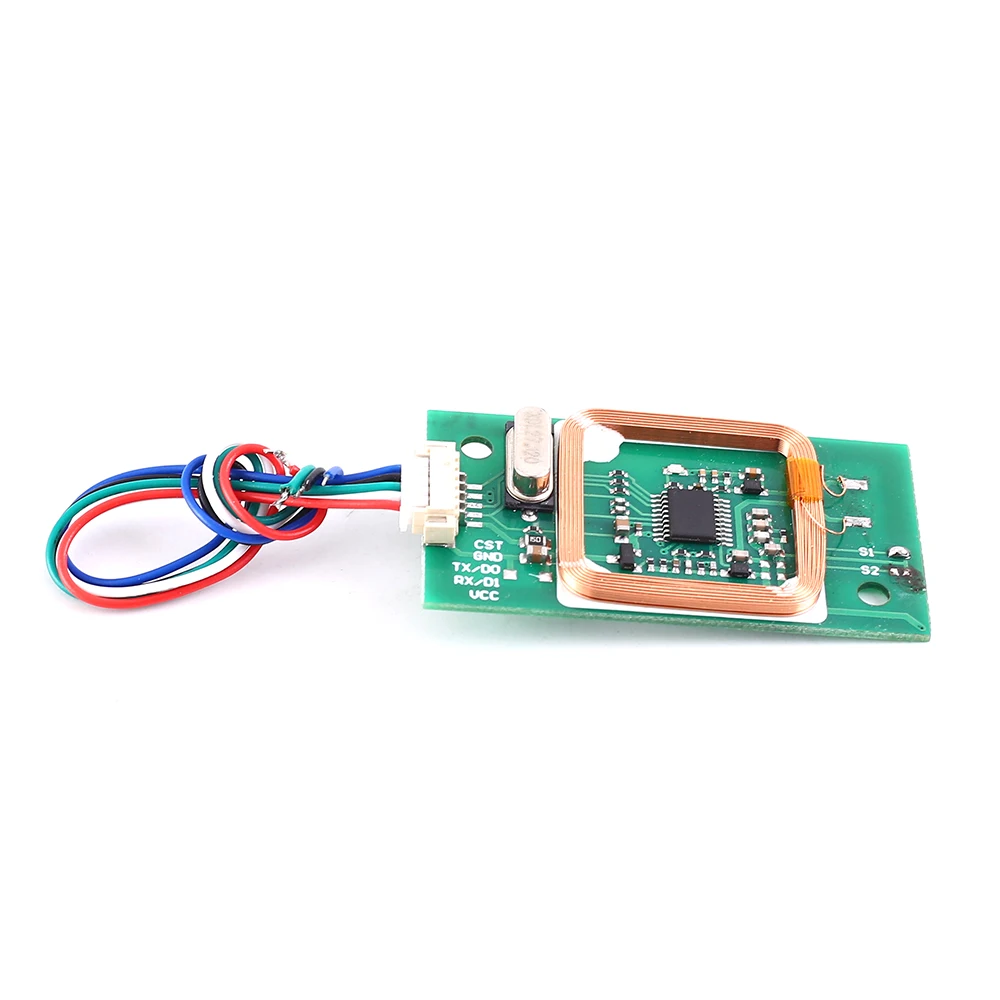
13.56Mhz reader Card
1.Description:It is a IC+ID dual frequency card reader module.It integrates a high-performance card reader RF circuit and antenna,replacing the Wiegand data output protocol.2.Feature:1>.Wigan dual format output2>.Support dual frequency RFID card3>.Support ID+IC card3.Description:1>.Product Name:IC+ID Dual Frequency Card Reader Module2>.Working Voltage:DC 5V3>.Working Current:40mA4>.Support Reading:125kHZ and 13.56MHZ card reading5>.Interface:Wiegand6>.Work Temperature:-35℃~85℃7>.Work Humidity:5%~95%RH8>.Size:47*26*5mm4.Wiegand Interface Output Introduction:1>.When a card is sensed,the serial number of the card will be output through the two data lines Data0 and Data1.2>.Data0 and Data1 are high replacements without data output.3>.Data bit 0 produces a 400us width concatenation on the Data0 line.4>.Data bit 1 produces a 400us width concatenation on the Data1 line.5>.The length of each bit of data is 2400us.6>.Each Mifare card has a serial number of 4 bytes,and we output the last three bytes.7>.The first 12 even parity digits are added to the front and the last 12 odd parity digits are added to the back,for a total of 26 bits of data.8>.E.g:The card number is:6B 3D 12 D6The output data is:3D 12 D65.Applicable:1>.Attendance fingerprint reader module2>.Access control intercom card reader module6.Package:1>.1pc IC+ID Dual Frequency Card Reader Module2>.1pc Wire


 SKU: n/a
 -
Sensor And Modules, Students Corner
13.56Mhz reader Keychain
Description
RFID card or RFID ring is used for sensing and identifying tagged people and objects for access control, automation, and a whole range of different applications. This basic RFID tag works in the 13.56Mhz RF range and comes with a uniqueID. It is not re-programmable. This blank, smooth, and the mildly flexible RFID tag is ready for your logo (or hand-drawn scribble).

Specifications and Features of RFID key ring:
- The Response frequency: 13.56 Mhz
- Size: 40.5 mm * 32 mm * 4.2 mm
- Material: ABS.
- Chip type: FM1108 Fudan Chip, sensing short is 2-5 m
- Memory capacity: 8 kbit
Package includes:
1x RFID Ring
SKU: n/a -
Sensor And Modules, Students Corner
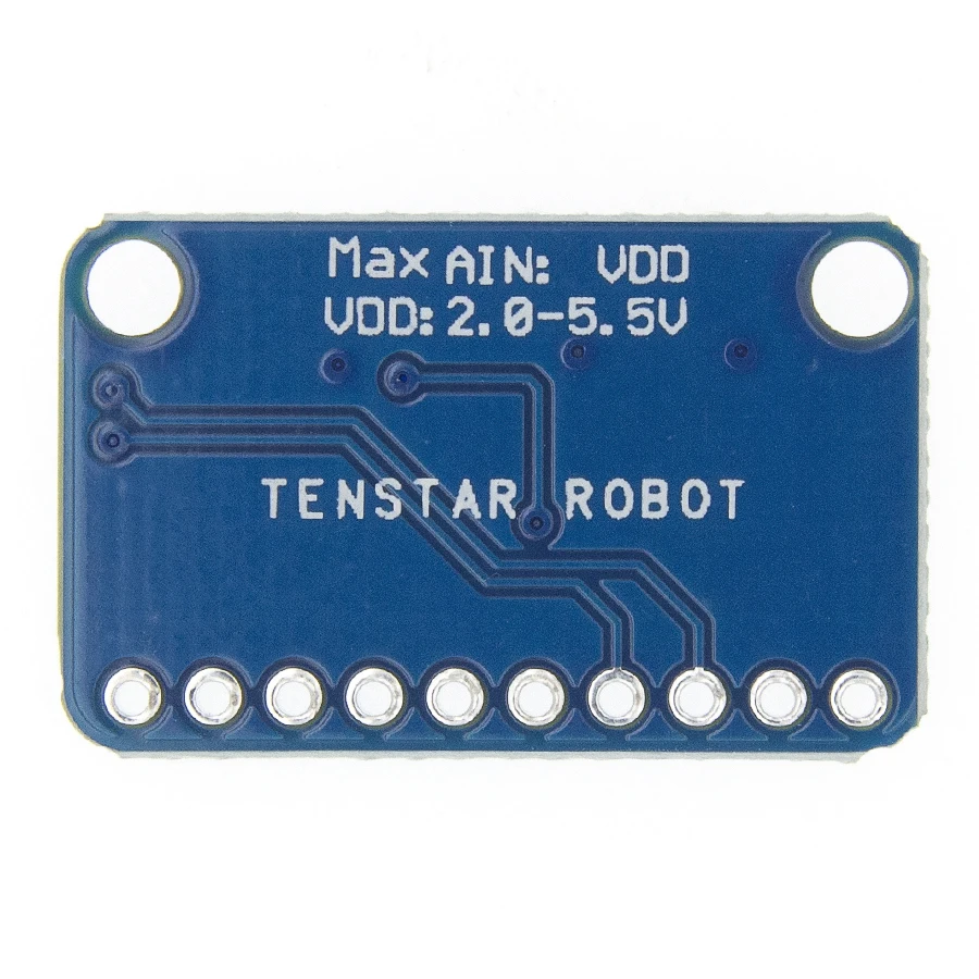
16 Bit I2C ADS1115 Module ADC 4 Channel with Pro Gain Amplifier
ADC Bit rate: 16 Bit
Interface Type: I2CChannels: 4 Channel AN0 AN1 AN2 AN3 or 2 differential inputsInput voltage: 2.0-5.5vChannel input voltage :0-VDDContinuous Mode: Only 150μASingle-Shot Mode: Auto Shut-DownPROGRAMMABLE DATA RATE:8sps-860spsInput range programmed control, 7 types input ranges:-0.256V ~ + 0.256V, -0.512V ~ + 0.512V, -1.024V ~ + 1.024V,-2.048V ~ + 2.048V, -4.096V ~ + 4.096 V, -6.144V ~ + 6.144VI2C 7-bit addresses between 0x48-0x4BSize:18mm*28mmApplicationsPortable instrumentationConsumer goodsBattery monitoringTemperature measurementFactory automation and process controls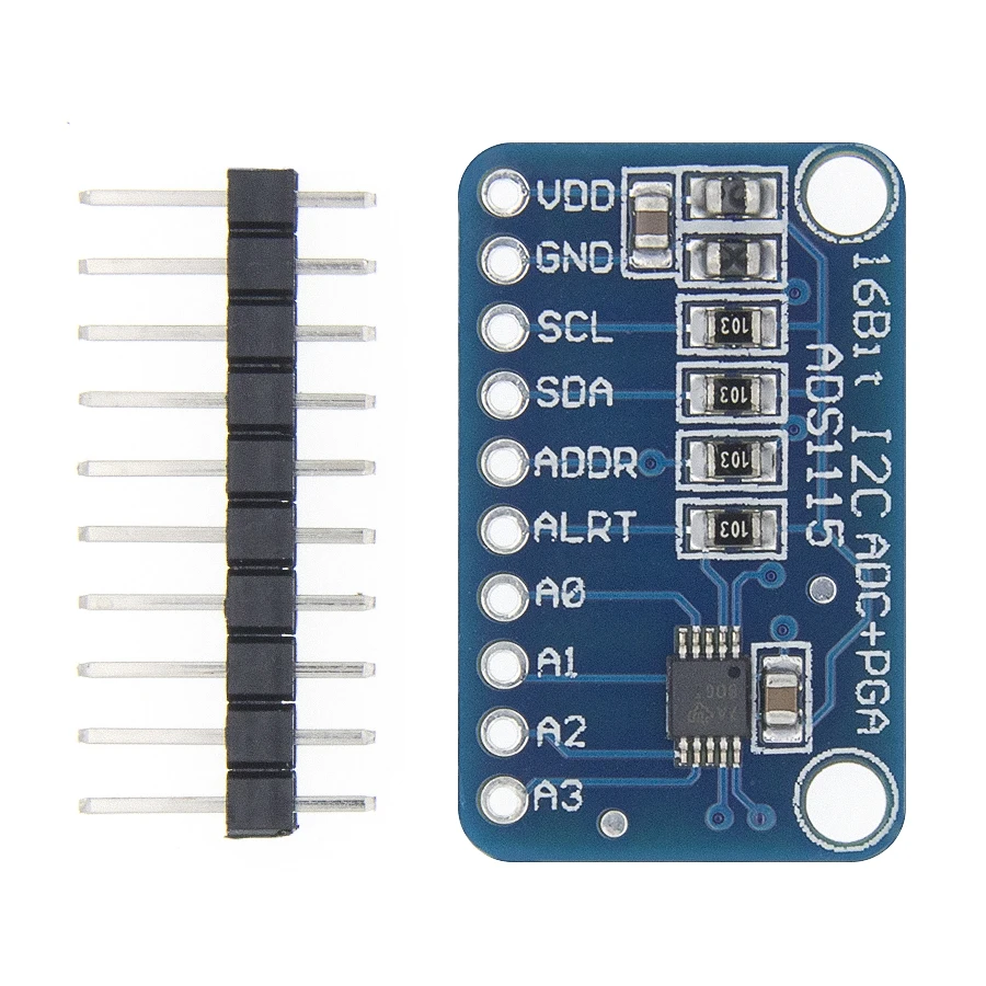
 SKU: n/a
 -
Sensor And Modules, Students Corner
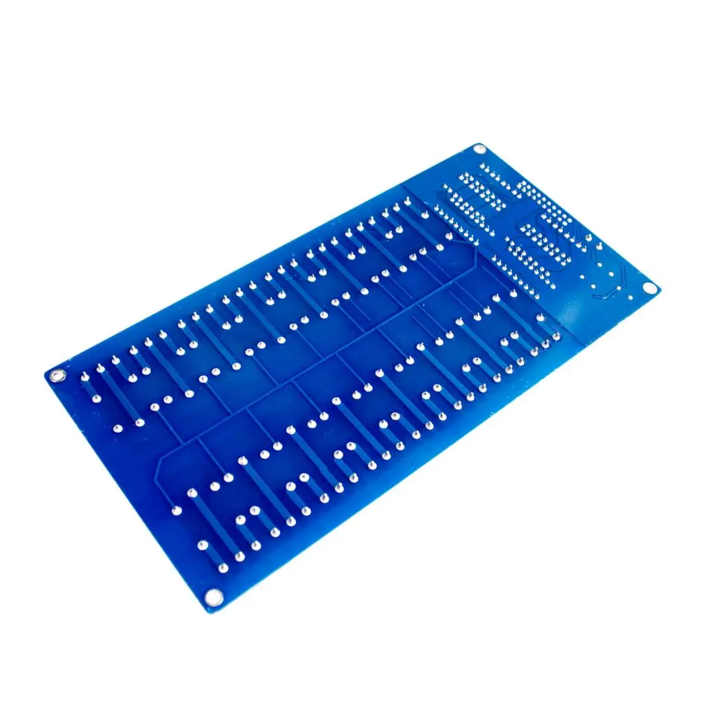
16 Channel Relay Module Board For Arduino
12V 16 Channel Relay Module Interface Board For PIC ARM DSP PLC With Optocoupler Protection LM2576 Power
Description:
Brand new and high quality.· 12V 16-Channel Relay interface board, and each one needs 15-25mA Driver Current.
· Equiped with high-current relay, AC250V 10A;DC30V 10A.
· Standard interface that can be controlled directly by microcontroller (for , 8051, AVR, PIC, PLC,DSP, ARM, ARM, MSP430, TTL logic).
· Indication LED\\\’s for Relay output status.
· Size:18cm x 9cm x 1.8cm (5.47inch x 2.04inch x 0.67inch).
Package Included:
1 x 16 Channel 12V Relay Module


 SKU: n/a
 -
Sensor And Modules, Students Corner
3 USB Mini Charging Module
 Description:
1. The module has two USB charging interfaces and one USB charging interface without protocol. Output maximum current 4A, with over-current protection function.
2. USB protocol charging interface can automatically identify the type of charging device, and shake hands with the device through the corresponding USB charging protocol, so as to obtain the maximum charging current and save charging time on the premise of protecting the charging device. It can charge most mobile phones in for Apple, for Samsung and other markets.
Specification:
Input voltage: DC 5.6-14V
Output voltage: DC 4.8-5.6V adjustable, default 5V
Maximum output current: 4A
Output overcurrent protection: when the output current is detected to be greater than 4A, stop the output immediately
Input overcurrent protection: if the input current is greater than 2A, stop the output immediately
Short circuit protection: Yes
Built in protocol: Divider1/Divider2/Divider3 charging protocol (for Apple); D + / D- set to 1.2V mode (for Samsung); BC1.2DCP and CTISYD/T1591-2009 charging protocol
Product size: 39 * 38 * 16mm/1.53*1.49*0.62”
Operation Description:
1. There are three USB interfaces on the module. The identification “Auto 2.4W” indicates that the USB port automatically recognizes the type of charging device, and “noIC” indicates that the USB port does not recognize the charging device. Devices that require a protocol to charge, such as for iPhone, can only be charged at the “Auto 2.4W” USB port.
2. The input voltage range of the module is within DC 5.6-14V, and the maximum output current is 4A. If it exceeds 4A, the module will automatically shut down the output. In order to protect the rear module, the input terminal has a 2A self recovery fuse. When the input current exceeds 2A, the fuse becomes high resistance and the output is closed. Therefore, if the output current is relatively large, the input voltage should be appropriately increased and the input current reduced. For example, to output 5V 3A, the input voltage should be greater than 7.5V (3A * 5V / 2A).
3. The module has an adjustable potentiometer, which can adjust the output voltage (4.8-5.6) V ± 0.3. The adjustable range may be different for different input voltage.
Note:
Please allow 1-3mm differs due to manual measurement.
Due to the different display and different light, the picture may not show the actual color of the item. Thanks for your understanding. 1 X Step Down Power Bank Board


 SKU: n/a
 -
Sensor And Modules, Students Corner
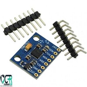
3-Axis Accelerometer Module GY-521 MPU-6050
Description
A 3-axis gyroscope and a 3-axis accelerometer are combined together on the same silicon die with an onboard Digital Motion Processor. Easy to get it fit into your project! It is very accurate, as GY-521 Mpu6050 Module contains 16-bits analog to digital conversion hardware for each channel. Therefor Three axis Gyrometer captures the x, y, and z channel at the same time. The sensor uses the I2C-bus to interface with the Arduino.
Features And Specifications Of GY-521 MPU6050 3 Axis Digital gyro + Accelerometer Three dimensional Angle sensor for Arduino:
- Build in ultra low noise linear LDO voltage regulator
- Build-in on board filters, which reduce noise from motor and other high current electronics
- All sensors connected to I2C bus
- You can easily select two I2C address for MPU6050 by soldered jumper
- Tri-Axis angular rate sensor (gyro) with a sensitivity up to 131 LSBs/dps and a full-scale range of ±250, ±500, ±1000, and ±2000dps
- Tri-Axis accelerometer with a programmable full scale range of ±2g, ±4g, ±8g and ±16g
- Digital Motion Processing™ (DMP™) engine offloads complex MotionFusion, sensor timing synchronization and gesture detection
- Embedded algorithms for run-time bias and compass calibration. No user intervention required
- Power LED
- Input Voltage: 2.3 – 3.4V
- Build in Logic level converter for I2C
- Digital-output temperature sensor
- Dimensions 20x16mm
- Designed for 5V logic level
Package Includes:
- 1 x GY521 MPU6050 Module 3 Axis Gyroscope Accelerometer Module
Best online shopping website for GY521 MPU6050 3 Axis Digital Gyroscope Accelerometer Sensor Module at cheap price in Lahore Faislabad Multan Quetta Sargodha Rahim Yar Khan Sialkot Sahiwal Gujrat Attock Gojra Sheikhpura Jahng Khanewal Okara Kasur Karachi and all over Pakistan


 SKU: n/a
 -
Sensor And Modules, Students Corner
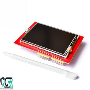
3.5 inch LCD Touch Screen Display with HDMI for Raspberry Pi
3.5 Inch TFT LCD Touch Screen Display 320×240 SPI Interface 16 Bits 5V RPI LCD (A) V3 Touch Screen For Raspberry Pi P1 P2 P3
description:Size: 3.5 inchesPCB size: 55.6*85.42mmResolution: 320×240Touch IC: xpt2046LCD IC: ili9486 ili9488 R61581Interface: SPIVoltage: 5VApplicable models: Raspberry Pi P1 P2 P3Bit width: 16 bitsPackage Included:1×3.5 inch touch TFT LCD display, suitable for Raspberry pi (excluding Raspberry pi)SKU: n/a -
Sensor And Modules, Students Corner
3D Printer Smart Controller, Ramps 1.4 LCD 12864 Control Panel
3D Printer Small Parts Kit Ramps 1.4 Controller 12864 Control Panel LCD Screen Monitor Blue Motherboard Display Module.
3D printers use LCD control panel, they are ramp extension accessories. LCD control panel through which you can achieve spooling, the 3D model G code files are copied to the SD card, and then print the file through the LCD control panel. This version is an improved version of the reprap smart controller.Package includes: 1x 12864 LCD driver printed circuit board
SKU: n/a -
Sensor And Modules, Students Corner
4 Channel NIC2262/2272 Wireless Remote Control with Receiver Module
 Sensor And Modules, Students Corner
4 Channel NIC2262/2272 Wireless Remote Control with Receiver Module
4 Channel RF Remote Transmitter and Receiver allows to remotely control four appliances. RF Remote Control provides 4 momentary outputs that can be wired to relays and control home appliances, lights, motors, light dimmers, robotic devices, RC cars, computer, etc. RF transmitter provides up to 150m range. Selection of custom address codes allows to operate more than one remote control system in the same area or to control one receiver with multiple transmitters. If required momentary outputs can be converted to toggle with low cost digital 4013 IC.
Specifications
- 4 Momentary Outputs
- 150m Transmission Range
- Rock-solid oscillator provides reliable operation
- Valid transmission LED status through VT connection
- High noise immunity
- Standard header connection (breadboard compatible)
- Selection of custom address codes allows to operate more than one unit in the same area or controlling the same receiver with multiple remotes
RF Transmitter Specifications
- Voltage Supply: 12V (Included 27A Alkaline Battery)
- Transmission Frequency: 433MHz
- Transmission Range: 150m
- Dimensions: 62 mm x 38 mm x 14 mm
RF Receiver Specifications
- Voltage Supply: 5V
- Transmission Frequency: 433MHz
- Output Mode: Momentary
- Power Consumption: 5 mA
- Receiving Sensitivity: -101 dbm
- Output PINs: GND, 5V, D0, D1, D2, D3, VT (Status LED)
- Dimensions: 41 mm x 22 mm x 6 mm
Receiver connect:
- VT: Decoding valid indication output pin
- D0-D3: Four control signal output pins
- VCC: + 5V
- GND: – Negative Electrode
SKU: n/a - 4 Momentary Outputs
-
Sensor And Modules, Students Corner
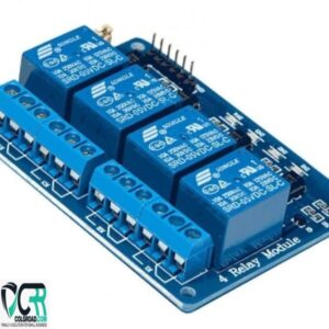
4 Channel Relay Module Board For Arduino
- 5V 4-Channel Relay interface board, and each one needs 15-20mA Driver Current
- Equipped with high-current relay, AC250V 10A ; DC30V 10A
- Standard interface that can be controlled directly by microcontroller (Arduino , 8051, AVR, PIC, DSP, ARM, ARM, MSP431, TTL logic)
- Indication LED’s for Relay output status
SKU: n/a