
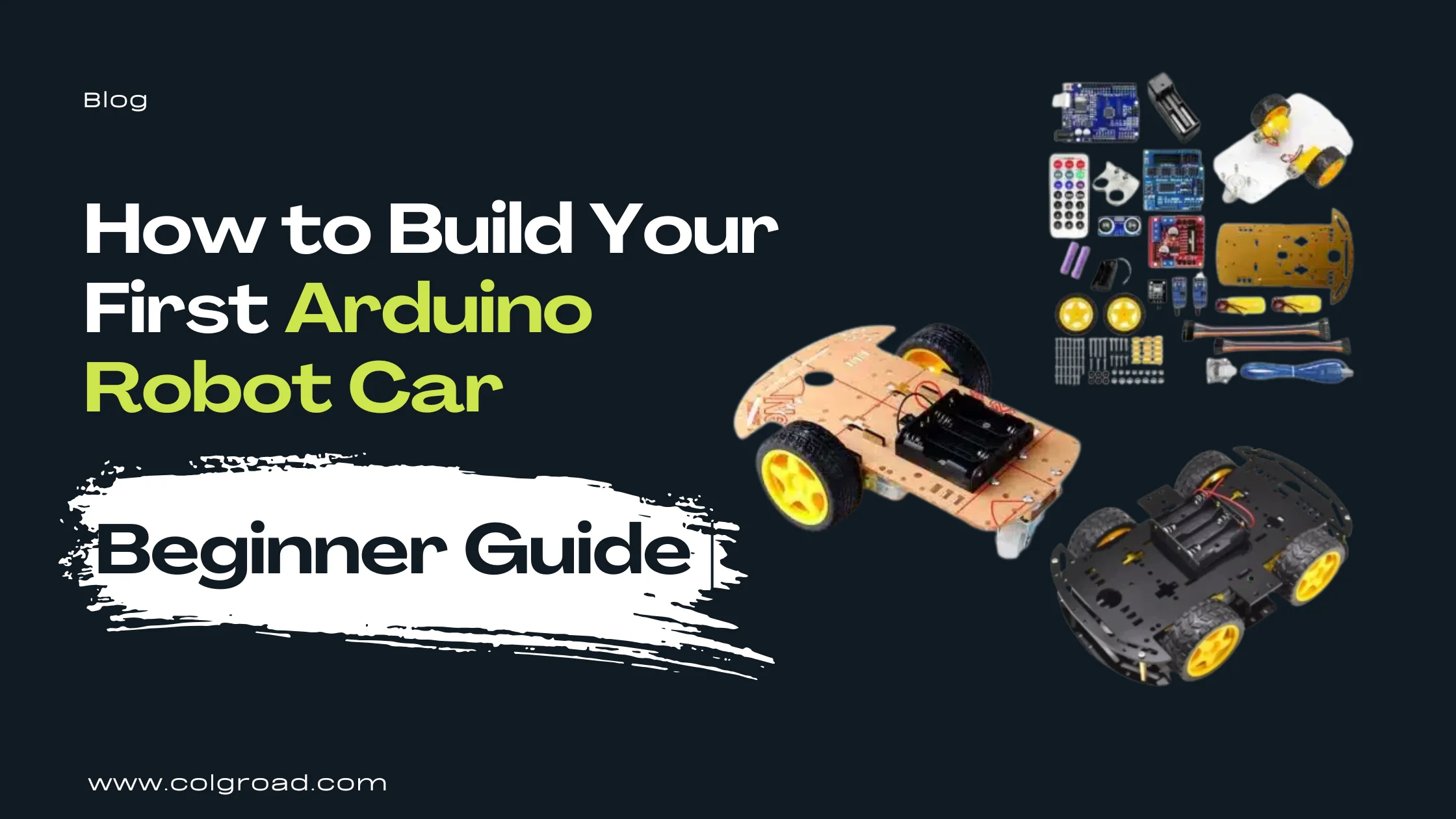
Building an Arduino robot car is one of the most rewarding projects for anyone starting their journey into robotics and electronics. Whether you are a student preparing for a science exhibition, a hobbyist exploring automation, or simply curious about how robots work, this guide will walk you through everything you need to know to build your first robot car from scratch.
By the end of this guide, you will understand how robot cars work, which components you need, how to assemble the hardware, how to write basic Arduino code for motor control, and how to expand your robot with features like obstacle avoidance, line following, and Bluetooth control.
What is an Arduino Robot Car?
An Arduino robot car is a small wheeled vehicle controlled by an Arduino microcontroller board. The Arduino acts as the brain of the robot, reading inputs from sensors and sending commands to motors based on the program you write. This combination of hardware and software control is the foundation of robotics.
The beauty of Arduino robot cars lies in their simplicity and expandability. You start with a basic chassis and motors, add an Arduino board and motor driver, and suddenly you have a moving robot. From there, you can add sensors for obstacle detection, line following, remote control via Bluetooth, and much more.
For students and beginners in Pakistan, Arduino robot cars provide hands-on experience with concepts taught in physics (motors, voltage, current), computer science (programming logic, algorithms), and engineering (mechanical assembly, circuit design). This practical application makes abstract concepts tangible and memorable.
Understanding the Core Components
Before building your robot car, you need to understand what each component does and why it matters. Every Arduino robot car consists of these essential parts:
The chassis is the physical structure that holds all other components together. It includes mounting plates, motor brackets, and space for electronics. Chassis come in 2WD (two-wheel drive) and 4WD (four-wheel drive) configurations. 2WD is simpler and recommended for beginners.
These motors convert electrical energy into rotational motion that spins the wheels. Gear motors include built-in gearboxes that reduce speed while increasing torque, giving your robot enough power to move even on surfaces with some resistance.
Rubber wheels attach to the motor shafts and provide traction. Most kits include wheels designed to fit the included motors. A caster wheel (small rotating wheel) at the front or back provides balance for 2WD robots.
The Arduino Uno is the most common choice for robot cars. It processes your program and sends control signals to the motor driver. The board has digital and analog pins for connecting sensors and other components.
Arduino pins cannot supply enough current to run motors directly. The motor driver acts as an intermediary, taking low-power signals from Arduino and providing high-power output to the motors. It also allows you to control motor direction and speed.
Batteries provide power to both the Arduino and motors. Common options include 18650 lithium cells, 9V batteries, or AA battery packs. The motor driver typically needs 6V to 12V depending on your motor specifications.
Choosing Between 2WD and 4WD
One of the first decisions you will face is whether to build a 2WD or 4WD robot car. Both have advantages, and your choice depends on your goals and experience level.
| Factor | 2WD Robot Car | 4WD Robot Car |
|---|---|---|
| Complexity | Simpler wiring and code | More wiring, slightly complex |
| Cost | Lower (fewer motors) | Higher (more components) |
| Power Consumption | Lower battery drain | Drains batteries faster |
| Traction | Good for smooth surfaces | Better grip, handles rough terrain |
| Speed Control | Easier to calibrate | Requires matching 4 motors |
| Best For | Beginners, first projects | Advanced projects, outdoor use |
Start with a 2WD robot car for your first project. It teaches you all the fundamental concepts with fewer variables to troubleshoot. Once you have built and programmed a working 2WD robot, upgrading to 4WD becomes much easier because you already understand the basics.
Option 1: Build From a Basic Chassis
Building from a basic chassis gives you maximum flexibility and deeper understanding of how each component works together. You select and connect each part individually, which is excellent for learning but requires sourcing components separately.
What You Get With a Chassis Kit
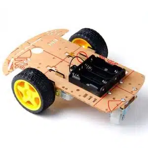
A basic chassis kit typically includes acrylic plates (top and bottom), DC gear motors with wheels, a caster wheel for balance, motor mounting brackets, screws and standoffs, and a battery holder. You will need to add an Arduino board, motor driver, jumper wires, and sensors separately.
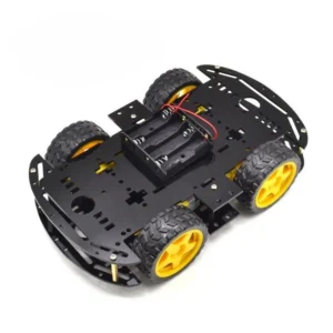
For projects requiring more power and stability, consider a 4WD chassis:
Additional Components Needed
When building from a basic chassis, you will also need: Arduino Uno board, L298N motor driver module, jumper wires (male to female and male to male), 18650 batteries or 9V battery with holder, and optionally sensors like ultrasonic (HC-SR04) for obstacle detection or IR sensors for line following.
Option 2: Start With a Complete Kit
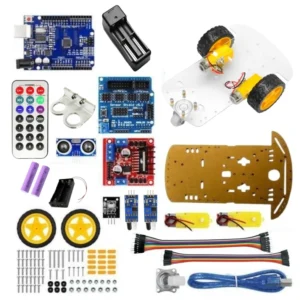
Complete kits include everything you need in one package: chassis, motors, Arduino board, motor driver, sensors, and wiring. This approach is faster, eliminates compatibility concerns, and often includes assembly instructions. For students working on school projects with deadlines, kits are the practical choice.
Benefits of Complete Kits
All components are tested to work together, reducing troubleshooting time. Kits often include sample code to get your robot moving quickly. You can focus on learning concepts rather than sourcing parts. Assembly instructions make the build process straightforward even for complete beginners.
Step-by-Step Assembly Guide
Whether you are building from a chassis or a complete kit, the assembly process follows similar steps. Take your time with each step and double-check connections before powering on.
Attach the DC motors to the motor brackets using the screws provided. Mount the brackets to the bottom acrylic plate. Install the caster wheel at the opposite end from the motors. If your kit has two plates, connect them using the standoffs to create space for electronics.
Secure the Arduino board to the top plate using screws or double-sided tape. Position the motor driver (L298N) near the motors to keep motor wires short. Mount the battery holder in an accessible location for easy battery changes.
Connect the left motor wires to OUT1 and OUT2 terminals on the L298N. Connect the right motor wires to OUT3 and OUT4 terminals. The polarity determines direction, so you can swap wires later if a motor runs backward.
Connect IN1 and IN2 from L298N to Arduino digital pins (such as pins 5 and 6). Connect IN3 and IN4 to pins 9 and 10. If using PWM speed control, connect ENA and ENB to PWM-capable pins. Connect the motor driver GND to Arduino GND.
Connect battery positive to the +12V terminal on L298N (despite the label, 6V to 9V works for most small motors). Connect battery negative to GND. If your motor driver has a 5V output, you can use it to power the Arduino through the 5V pin.
Press the wheels firmly onto the motor shafts. Before uploading code, verify all connections visually. Look for loose wires, incorrect polarity, or short circuits. Once satisfied, proceed to programming.
Always disconnect the battery before making wiring changes. Double-check motor driver connections before powering on, as incorrect wiring can damage the Arduino or motor driver. If motors do not spin or the board gets hot, disconnect power immediately and recheck your connections.
Your First Arduino Robot Car Code
With the hardware assembled, it is time to bring your robot to life with code. The following program demonstrates basic motor control, making your robot move forward, backward, turn left, turn right, and stop.
// Motor A (Left) connected to pins 5, 6
// Motor B (Right) connected to pins 9, 10
// Motor A pins
const int motorA1 = 5;
const int motorA2 = 6;
// Motor B pins
const int motorB1 = 9;
const int motorB2 = 10;
void setup() {
pinMode(motorA1, OUTPUT);
pinMode(motorA2, OUTPUT);
pinMode(motorB1, OUTPUT);
pinMode(motorB2, OUTPUT);
}
void moveForward() {
digitalWrite(motorA1, HIGH);
digitalWrite(motorA2, LOW);
digitalWrite(motorB1, HIGH);
digitalWrite(motorB2, LOW);
}
void moveBackward() {
digitalWrite(motorA1, LOW);
digitalWrite(motorA2, HIGH);
digitalWrite(motorB1, LOW);
digitalWrite(motorB2, HIGH);
}
void turnLeft() {
digitalWrite(motorA1, LOW);
digitalWrite(motorA2, HIGH);
digitalWrite(motorB1, HIGH);
digitalWrite(motorB2, LOW);
}
void turnRight() {
digitalWrite(motorA1, HIGH);
digitalWrite(motorA2, LOW);
digitalWrite(motorB1, LOW);
digitalWrite(motorB2, HIGH);
}
void stopMotors() {
digitalWrite(motorA1, LOW);
digitalWrite(motorA2, LOW);
digitalWrite(motorB1, LOW);
digitalWrite(motorB2, LOW);
}
void loop() {
moveForward();
delay(2000); // Move forward for 2 seconds
stopMotors();
delay(500);
turnRight();
delay(500); // Turn right for 0.5 seconds
stopMotors();
delay(500);
}
Understanding the Code
The code defines functions for each movement direction. Setting one motor pin HIGH and the other LOW makes the motor spin in one direction. Reversing these values reverses the motor. The loop function demonstrates a simple sequence: move forward, stop, turn right, and repeat. Adjust the delay values to change how long each action lasts.
Expanding Your Robot: Project Ideas
Once your basic robot car moves as expected, you can add sensors and features to make it more intelligent. Here are popular expansion projects:
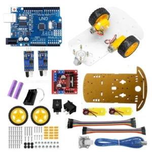
Add IR sensors pointing downward to detect a black line on a white surface (or vice versa). The robot follows the line by adjusting motor speeds based on which sensor detects the line. This project teaches sensor integration and conditional logic.
For a dedicated line following project with all components included:
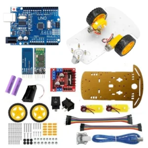
Mount an ultrasonic sensor (HC-SR04) at the front of your robot. The sensor measures distance to objects ahead. When an obstacle is detected within a threshold distance, the robot stops, looks left and right using a servo motor, and turns toward the clearer path.
Add an HC-05 or HC-06 Bluetooth module to control your robot from a smartphone app. This transforms your autonomous robot into a remote-controlled vehicle, combining the learning from previous projects with wireless communication concepts.
Troubleshooting Common Problems
Even experienced builders encounter issues. Here are solutions to the most common problems:
Robot Does Not Move At All
Check that batteries are charged and properly connected. Verify the motor driver is receiving power (most L298N modules have a power LED). Confirm Arduino is powered and running your program (the onboard LED should indicate activity). Check all wire connections, especially ground connections between Arduino and motor driver.
One Motor Works, The Other Does Not
The non-working motor may have a loose connection. Swap the motor connections to test if the problem follows the motor or stays with the motor driver output. If the problem follows the motor, check that motor's wiring. If it stays with the output, the motor driver channel may be damaged.
Robot Moves But Curves to One Side
Motors have slight manufacturing variations causing different speeds. Use PWM (analogWrite) instead of digitalWrite to control motor speeds, then adjust values until the robot drives straight. This calibration process teaches valuable lessons about real-world hardware variations.
Motors Run But Robot Moves Backward When Told to Go Forward
Motor polarity is reversed. Either swap the two wires for that motor at the motor driver terminals, or swap the HIGH and LOW values for that motor in your code. Both solutions achieve the same result.
Robot Moves Erratically or Resets
This usually indicates power supply issues. Motors draw significant current when starting, which can cause voltage drops that reset the Arduino. Use separate power sources for motors and Arduino, or add capacitors across the motor driver power input to smooth voltage fluctuations.
Tips for School Projects and Exhibitions
Document your process. Take photos and notes during building. Judges and teachers appreciate seeing your journey from components to working robot.
Prepare a demonstration track. For line followers, bring your own track with clean, consistent lines. For obstacle avoiders, bring boxes or obstacles of known sizes.
Have a backup plan. Bring extra batteries, spare wires, and a copy of your code. Technical issues happen, and being prepared shows professionalism.
Explain the concepts. Be ready to explain how each component works and why you made certain design choices. Understanding matters more than just having a working robot.
Practice your presentation. Run through your demonstration multiple times before the exhibition. Know how long your batteries last and what conditions affect your robot's performance.
What to Learn Next
Building your first Arduino robot car opens doors to many advanced topics. Consider exploring these areas as you gain confidence:
PID Control: Learn proportional-integral-derivative algorithms for smoother, more precise line following and motor control.
Sensor Fusion: Combine multiple sensors (ultrasonic, IR, accelerometer) for more reliable navigation decisions.
Wireless Communication: Move beyond Bluetooth to WiFi control with ESP32, enabling web-based interfaces and IoT integration.
Computer Vision: Add a camera module and explore image processing for object recognition and advanced navigation.
Mechanical Design: Learn CAD software to design custom chassis and 3D print specialized parts for your robots.
Browse All STEM and DIY Learning Kits