
You have a Uni-T meter in your hand, three sockets at the bottom, a dial with more symbols than you expected, and a project on the bench that is not working. The manual that came in the box lists ranges but does not tell you where to put the black lead first. This post settles that. It walks you from the leads and sockets to a real voltage reading, a continuity beep on a broken wire, a resistance check on a resistor, and the two or three habits that stop beginners from blowing the fuse.
How do you use a Uni-T multimeter step by step?
To use a Uni-T multimeter, plug the black lead into COM and the red lead into the V/Ω socket, turn the dial to the range you need, touch the probes across the point you are testing, and read the display. Start on the highest range when unsure, and never measure resistance or continuity on a powered circuit.
What do the sockets and dial positions on a Uni-T multimeter mean?

The sockets tell you where each lead goes, and the dial tells the meter what to measure. Get these two right and most of the work is done before you touch a single probe to a circuit.
On a typical Uni-T handheld meter you will see three sockets along the bottom:
- COM – the common socket. The black lead always goes here, on every measurement, without exception.
- V/Ω/mA (sometimes marked VΩmA or just VΩ) – the red lead goes here for voltage, resistance, continuity, diode and low current checks.
- 10A (or 20A) – the red lead goes here only when you are measuring high current, and only after you have moved it back afterwards.
The dial is a rotary selector. The main positions you will use as a beginner are:
| Dial symbol | What it measures | Typical use |
|---|---|---|
| V with a straight line (V⎓) | DC voltage | Batteries, Arduino pins, power supply outputs |
| V with a wave (V~) | AC voltage | Wall sockets, transformer outputs |
| Ω | Resistance | Resistors, coils, checking for open circuits |
| Diode / buzzer symbol | Continuity and diode drop | Finding broken wires, checking diodes |
| A⎓ or A~ | Current | Measuring how much a circuit draws |
Some Uni-T models are auto-ranging, which means you pick the function and the meter chooses the range. Others have numbered ranges you select yourself. If yours has numbers, start high and work down. A reading of 0.00 on a range that is too small usually means you need the next range up, not that the circuit is dead.
If you are shopping for your first meter, our DT830D Digital Pocket Size Multimeter with Probes (DMM) at Rs. 750 covers DC voltage up to 1000V, AC up to 750V, resistance up to 2 MΩ and a continuity buzzer, which is enough for most student projects. The full range of meters and bench tools sits in our Tech Tools and Instruments category.
What do you need before you start measuring?
You need the meter, its two probes, a known working battery to practise on, and a clean, dry bench. That is it for the first session.
- A Uni-T digital multimeter with its red and black test leads.
- A known good battery, such as a fresh AA cell or a 9V battery, so you can confirm the meter reads something sensible before you trust it on a real circuit.
- A resistor or two with the colour bands readable, so you can compare the measured value against the marked value.
- A scrap piece of wire or a spare jumper lead for the continuity test.
- Insulated probes in good condition. Cracked insulation or a loose probe tip is a safety problem, not a minor annoyance.
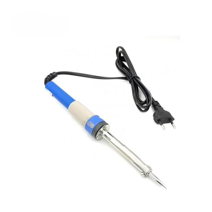
If you are also soldering the board you are testing, keep the Soldering Iron 220V 40W and 60W at Rs. 750 and a spool of Hi Flow DIA 0.8mm Soldering Wire (50g) at Rs. 260 nearby, and tie your test leads out of the way with a Cable Tie 4-16 Inches China pack at Rs. 100 so they do not drag across a hot joint.
How do you measure DC voltage and AC voltage safely?
For DC voltage, put the black lead in COM, the red lead in V/Ω, turn the dial to DC volts, touch the black probe to ground and the red probe to the point you want to measure, then read the display. For AC voltage, do the same but select the AC volts position.
Practise on a battery first. A fresh AA cell should read close to 1.5V, and a 9V battery close to 9V. If your reading is wildly different, check the dial position and the socket before you suspect the battery.
On an Arduino or ESP32 board, the safe order is:
- Clip or hold the black probe on a ground pin (GND).
- Touch the red probe to the 5V or 3.3V pin to confirm the supply is present.
- Move the red probe to the signal pin you are debugging.
For AC, treat every wall socket as live. Set the meter to AC volts, confirm the range is above the expected voltage, and keep your fingers behind the probe guards. In Pakistan the mains supply is nominally 220V – 230V, so a 750V AC range on a student meter is comfortable. Never probe a live socket with the meter set to resistance, continuity or current.
One habit worth building: after every measurement, move the red lead back to the V/Ω socket and turn the dial to OFF or to DC volts. That single step prevents most accidental fuse blows.
How do you test continuity and find a broken wire?
Turn the dial to the continuity or diode symbol, touch the two probe tips together, and listen for the beep. Then touch the probes to the two ends of the wire you are checking. A beep means the path is complete; silence means it is broken.
Continuity mode is the fastest way to find a break in a jumper lead, a USB cable or a PCB trace. Work through it in this order:
- Prove the meter first by touching the probes together. No beep here means a flat battery or a bad lead, not a bad cable.
- Touch one probe to each end of the same conductor. Beep means the conductor is good.
- If there is no beep, flex the cable gently while holding the probes in place. A beep that comes and goes points to an intermittent break, usually near the connector.
- Repeat for each conductor in a multi-core cable, and note which pin goes where.
Continuity only works on a dead circuit. Switch the power off and, where there are capacitors, let them discharge before you probe. A meter in continuity mode on a live circuit can give false readings and can damage the meter.
For network and data cabling, a dedicated tester is faster than a multimeter because it checks all pairs at once. Our guide on how to use a network toner and probe kit covers that workflow, and the same logic of proving the tool before trusting the result applies.
How do you measure resistance and check a resistor?
Switch the circuit off, select the resistance range, touch one probe to each end of the resistor, and read the value. Compare it with the colour bands, allowing for the resistor’s tolerance.
Resistance is measured in ohms (Ω), and most student projects use values from a few ohms up to hundreds of kilohms. A few practical points:
- Never measure resistance on a powered circuit. The meter sends a small current through the component, and an external voltage will corrupt the reading and can damage the meter.
- Measure out of circuit where you can. A resistor in a board may read lower than its marked value because other components sit in parallel with it.
- Hold the probes by the insulated handles. Your fingers across both probe tips add your own body resistance to the reading, which matters on high values.
- Watch for OL or 1 on the display. That means over-range or an open circuit, not a value of one ohm.
A resistor that reads far above its band value, or shows OL, is usually open and should be replaced. A resistor that reads noticeably low is often fine and just sitting in parallel with something else, so lift one leg and measure again before you condemn it.
How do you check a diode or transistor with the meter?

Use the diode position: a good silicon diode reads a forward drop in the region of 0.5V – 0.7V one way and shows OL the other way. A transistor is checked as two diodes sharing a base.
For a diode:
- Set the dial to the diode symbol.
- Touch the red probe to the anode and the black probe to the cathode. Note the forward reading.
- Swap the probes. The meter should show OL or a very high value.
- A diode that reads near zero both ways is shorted. One that reads OL both ways is open.
For a small signal transistor, identify the base, collector and emitter from its datasheet, then test the base-emitter and base-collector junctions as two diodes. Both should conduct one way and block the other. This catches most dead transistors in a student project without needing a component tester.
If you are checking temperature sensors rather than semiconductors, our post on how to check a K type thermocouple with a multimeter covers the millivolt readings you should expect.
What are the most common beginner mistakes that damage a meter?
The classic mistake is leaving the red lead in the current socket and then measuring voltage, which shorts the supply through the meter’s fuse. The second most common is measuring resistance or continuity on a live circuit.
Here are the habits that prevent almost all of it:
- Return the red lead to V/Ω after every current measurement. Make it automatic, like putting on a seatbelt.
- Check the dial before you probe. Voltage position for voltage, resistance position for resistance, and never the other way round.
- Start on a higher range than you expect. An over-range reading is harmless; a range that is too low can be confusing and, on current, damaging.
- Keep the meter dry and cool. Rawalpindi summers are hard on electronics, so store the meter in a shaded, dry place rather than a hot car or a damp toolbox.
- Do not probe mains with cheap probes. Use the meter only within its rated voltage and keep your hands behind the finger guards.
- Do not force the dial or the sockets. If a lead will not seat, check for a bent pin rather than pushing harder.
If the meter reads nothing at all, check the battery before anything else. A weak battery is the most common reason a working meter appears dead.
How do you replace the battery and fuse in a Uni-T meter?
Disconnect the leads, switch the meter off, remove the two screws on the back case, lift the cover, and replace the battery or fuse with the same type and rating printed inside the case. Reassemble and test on a known battery before using it on a circuit.
Two rules matter here:
- Match the fuse exactly. The correct current rating and voltage rating are marked on the case or the old fuse. A higher-rated fuse protects nothing.
- Watch the battery polarity. The spring contact is usually the negative end. Reversed cells can leak and damage the board.
If the meter still misbehaves after a fresh battery and a correct fuse, stop using it on anything live and bring it to us. We are on College Road in Rawalpindi and we deliver across Pakistan at a flat Rs. 350 shipping rate, so you can also send it to us with a note on what it is doing. Message us with your meter model and the symptom, and we will tell you what to check next.
Frequently asked questions
How do I use the UNI-T UT681L cable tester to check network cables?
Plug one end of the cable into the main unit and the other into the remote terminator, then switch on and watch the pin indicators. All pins should light in sequence on both units. A pin that stays dark means an open conductor, and a pin that lights out of order means a miswired pair. Test a known good patch lead first so you know the tester itself is working.
How do I use the UNI-T UT204+ for electronics troubleshooting?
The UT204+ is a clamp meter, so it measures current by clamping around a single conductor rather than breaking the circuit. Set it to the DC or AC current range, clamp one wire only, and read the value. Use the test leads for voltage and continuity checks in the usual way. Clamping around both wires of a pair cancels the reading.
How do I use the UNI-T UT681C cable tester?
Connect the cable between the main unit and the remote, power on, and step through the test. The UT681C checks continuity and wiring order pin by pin. Compare the result against the expected straight-through or crossover wiring for your cable, and test a known good cable first to confirm the unit is functioning.
What is the difference between DC volts and AC volts on the dial?
DC volts is the straight-line symbol and is used for batteries, power supply outputs and microcontroller pins. AC volts is the wave symbol and is used for mains sockets and transformer outputs. Selecting the wrong one gives a misleading reading, so check the symbol before you probe.
Why does my multimeter show OL or 1?
OL or a lone 1 means over-range or an open circuit. On resistance and continuity, it usually means the path is broken or the component is open. On voltage, it means the selected range is too low for the voltage present, so move the dial up one range.
Can I measure current with the test leads instead of a clamp?
Yes, but only by putting the meter in series with the circuit and moving the red lead to the current socket. This is where most beginners blow a fuse, because leaving the lead in the current socket and then measuring voltage creates a short. A clamp meter avoids that risk entirely.
