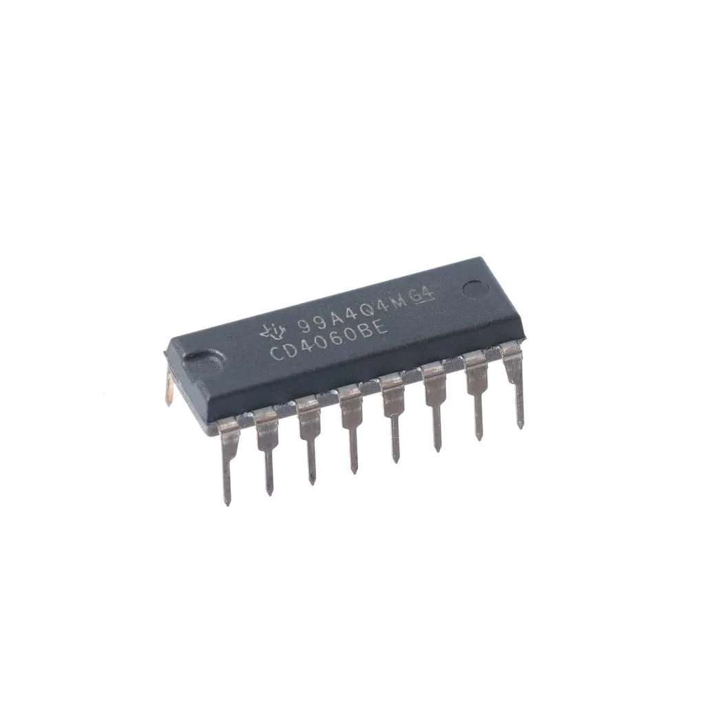
Overview: CD4060 14-Stage Binary Counter IC (DIP)
The CD4060 is a versatile 14-stage ripple-carry binary counter IC with a built-in oscillator, packaged in a standard DIP footprint. It combines a binary counter and an oscillator on one chip, making it an excellent choice for timer circuits, frequency division, clock generation, and rapid prototyping on breadboards.
Key Specifications
- Supply voltage: 3V to 15V (wide operating range for battery and industrial applications)
- Stages: 14-stage binary divider providing multiple binary output taps
- Frequency division: Typical division ratios from 2 to 16,384 depending on output tap
- Oscillator: On-chip oscillator requiring external resistor(s) and capacitor for R-C timing
- Package: Standard DIP for easy prototyping and socket mounting
- Technology: Low power CMOS with high noise immunity
Features
- Integrated 14-stage counter plus oscillator reduces component count
- Flexible oscillator configuration using external R and C components
- Operates across a wide 3V to 15V supply range
- Multiple binary output taps for a variety of division ratios
- Low quiescent current and high noise immunity suitable for battery-powered designs
- Standard DIP packaging for breadboards and development boards
Common Applications
- Frequency division and clock generation for digital systems
- Timer circuits, delay generators, and pulse stretching
- Sequential LED or LCD display control and multiplexing
- Digital counters and frequency measurement systems
- Automation, embedded control, and prototype development
Using the Built-In Oscillator
The CD4060’s oscillator accepts external resistor(s) and a timing capacitor to set the oscillation frequency. Typical implementation steps:
- Choose a timing capacitor (C) and resistor values (R) based on the desired base frequency.
- Connect R and C to the oscillator pins according to the CD4060 application schematic.
- Use the required output tap to obtain the divided frequency; each tap divides the base frequency by a power of two.
- If a precise clock is required, consider using a crystal or an external stable clock source instead of the R-C oscillator.
Design Notes and Best Practices
- Decouple the supply pins with a 0.1 µF ceramic capacitor close to the IC to improve noise immunity.
- For low-frequency timing, use a larger capacitor and appropriate resistor values; for higher frequencies, choose smaller R-C values and verify stability.
- Keep oscillator wiring short and avoid routing noisy signals near the timing components to prevent frequency jitter.
- Because the CD4060 is CMOS, observe ESD precautions during handling and assembly.
Ordering and Packaging
This CD4060 is supplied in a standard DIP package suitable for through-hole mounting and breadboard use. It is ideal for hobbyists, students, and engineers developing timing and frequency division circuits.
Note: Images are for illustration purposes only.


Reviews
There are no reviews yet