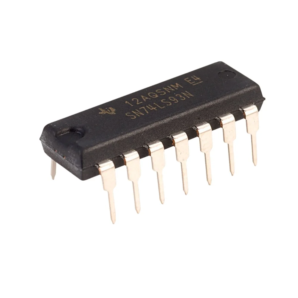
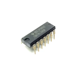
Overview: 7493 4-Bit Binary Counter IC (DIP)
The 7493 4-Bit Binary Counter IC is a TTL logic ripple counter that provides reliable binary counting from 0 to 15. Housed in a 14-pin Dual In-Line Package (DIP), the 7493 is breadboard-friendly and well suited for educational labs, digital electronics projects, frequency division, and sequence generation.
Key Features of the 7493 4-bit Binary Counter
- 4-bit binary counting: outputs Q0 to Q3 represent binary values 0000 to 1111 (0 to 15)
- Ripple counter architecture for simple asynchronous counting
- TTL logic compatible: designed for standard 5 V TTL systems
- Independent reset/clear inputs for custom count sequences and easy initialization
- DIP package (14 pins) makes it breadboard and through-hole PCB friendly
- External clock input allows use with oscillators, pulse generators, or other digital sources
Technical Specifications
- IC Type: Binary Counter
- IC Number: 7493
- Counter Bits: 4-Bit (Q0 to Q3)
- Logic Family: TTL
- Package Type: DIP (Dual In-Line Package)
- Number of Pins: 14
- Operating Voltage: 5 V (typical)
- Clock Input: External clock source required
- Output Type: Binary outputs Q0 to Q3
Typical Applications
- Digital counters and timers
- Frequency division and clock division circuits
- Digital clocks and display driving (use with BCD to 7-segment drivers or decoders)
- Educational and training kits for learning digital logic
- Sequence generation, control logic, and simple state machines
Advantages and Why Use the 7493
- Simple implementation of binary counting with very few external components
- Reliable TTL performance and easy integration with other 74xx series ICs
- Good choice for learning, prototyping, and low-cost digital projects
- Flexible reset and clock inputs for versatile applications
Integration and Usage Tips
- Power: Connect VCC to +5 V and GND to 0 V. Observe correct pin orientation on the DIP package.
- Clock: Provide an external TTL-compatible clock pulse to the clock input to advance the counter.
- Reset/Clear: Use the independent clear inputs to reset the counter to 0000 or to create nonstandard count sequences by controlling those pins.
- Decoupling: Place a 0.1 uF decoupling capacitor close to the VCC and GND pins to ensure stable operation.
- Interfacing: Drive LEDs through current-limiting resistors or interface to BCD-to-7-segment decoders for visual displays. To build wider counters, cascade multiple counters or use a higher-bit counter IC.
- Frequency Division: The 7493 can be used as a divide-by-N stage. Each output bit divides the input clock by powers of two, useful for generating lower frequency clocks.
Pinout Summary
- 14-pin DIP package: VCC, GND, clock input(s), reset/clear inputs, and outputs Q0 through Q3
- Refer to the component datasheet for the exact pin numbering and electrical characteristics before wiring in production or critical designs
Safety and Handling
- Use proper decoupling capacitors for stable operation under switching loads.
- Ensure correct supply voltage and verify pin connections before powering the IC.
- Follow ESD-safe handling practices to avoid damage to the IC.
Note: Images are for illustration purposes only. Actual IC manufacturer marking and appearance may vary slightly.


Reviews
There are no reviews yet