Overview
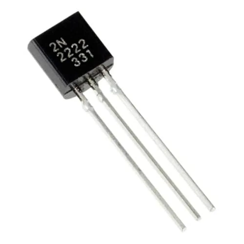
The 2N2222 NPN transistor is a widely used general-purpose bipolar junction transistor suitable for medium-power switching and linear amplification. With a maximum collector-emitter voltage of 60V and a maximum collector current of 0.8A, the 2N2222 provides greater drive capability than small-signal transistors such as the BC547 or BC548, while remaining compact and easy to prototype with in a TO-92 package.
Key Features
- NPN bipolar junction transistor for switching and amplification
- Collector-Emitter Voltage (Vce): 60V
- Collector Current (Ic): 0.8A maximum
- Maximum Power Dissipation: 500 mW
- DC Current Gain (hFE): typically 100 to 300 depending on operating point
- Package: TO-92 for easy mounting on breadboards and PCBs
- Fast switching suitable for PWM, digital logic, and some RF applications
Technical Specifications
- Transistor Type: NPN BJT
- Vce (max): 60 V
- Ic (max): 0.8 A
- Power Dissipation: 500 mW (ambient conditions, TO-92)
- hFE (DC Current Gain): 100 to 300 (varies with Ic and Vce)
- Package: TO-92 (through-hole)
Typical Applications
- General-purpose switching and small power amplification
- Relay and motor driver circuits (with appropriate base resistor and protection diodes)
- LED and lamp drivers
- PWM-based control systems for speed and brightness control
- Digital logic interfacing and level shifting
- Hobbyist robotics and automation projects
Using the 2N2222 in Circuits
When designing with the 2N2222, follow these practical guidelines:
- Always use a base resistor to limit base current and protect the transistor.
- For inductive loads such as relays or motors, place a flyback diode across the load to prevent voltage spikes from damaging the transistor.
- Keep the transistor within safe power dissipation limits; add heat sinking or use a different package if you need higher power handling.
- For switching applications, drive the base hard enough to saturate the transistor for low Vce(sat), but avoid excessive base current that may exceed the transistor limits.
Examples
- Driving a relay: use base resistor, flyback diode, and ensure Ic is within 0.8A limit.
- LED driver: use a resistor in series with the LED and select base resistor to switch fully.
- Simple amplifier: bias the transistor in the linear region and use coupling capacitors as needed.
Package and Prototyping
The TO-92 package makes the 2N2222 convenient for breadboard testing and straightforward PCB mounting. Pinouts may vary by manufacturer, so always check the datasheet for pin orientation when replacing parts.
Ordering and Notes
- Common, cost-effective transistor for education, prototyping, and production.
- Check manufacturer datasheets for specific curves, ratings, and guaranteed hFE ranges.
- Images are for illustration purposes only.


Reviews
There are no reviews yet