
Learning how to read circuit diagrams is one of the first steps toward understanding electronics. A circuit diagram (also called a schematic) is a visual map that shows how different components are connected. At first, all the symbols and lines may look confusing, but once you understand the basics, it becomes like reading a simple recipe.
In this guide, we’ll walk through the essentials of reading circuit diagrams as a beginner, breaking everything down into easy steps.
What Is a Circuit Diagram?
A circuit diagram is a symbolic drawing that represents the flow of electricity in a system. Instead of showing the physical placement of components, it uses standard symbols to describe how they connect and interact.
💡 Example: Think of a circuit diagram like a subway map. It doesn’t show the actual streets but instead uses symbols and lines to explain where each station (component) is and how they are connected.
Why Beginners Should Learn to Read Circuit Diagrams
- Foundation of electronics: Every electronic project, from a blinking LED to a smartphone, starts with a circuit diagram.
- Universal language: Engineers worldwide use standard symbols, so learning them means you can understand diagrams anywhere.
- Problem-solving tool: If a circuit isn’t working, the diagram helps you trace where things might have gone wrong.
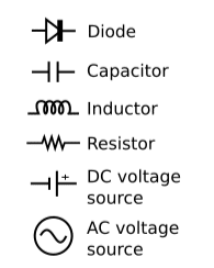
Common Symbols You’ll See in Circuit Diagrams
Symbols are the alphabet of electronics. Here are the most common ones every beginner should know:
Resistors
- Symbol: A zig-zag line (in some regions, a rectangle).
- Purpose: Limit current flow.
Capacitors
- Symbol: Two parallel lines (one may be curved).
- Purpose: Store and release electrical energy.
Diodes
- Symbol: A triangle pointing to a line.
- Purpose: Allow current to flow in one direction only.
Inductors
- Symbol: A series of curved loops or coils.
Purpose: Stores energy in the form of a magnetic field and resists changes in current.
Power Sources
- Symbol: A long line and a short line (battery), aka DC voltage source, or a circle with a plus and minus, aka AC voltage source.
- Purpose: Provide energy to the circuit.
💡 Example: If you see a zig-zag line next to a battery symbol, you know that’s a resistor limiting the flow from the power source.
Understanding Circuit Connections
Wires and Junctions
- Straight lines represent wires.
- Dots where wires meet show connections.
- Crossing lines without a dot means the wires don’t connect.
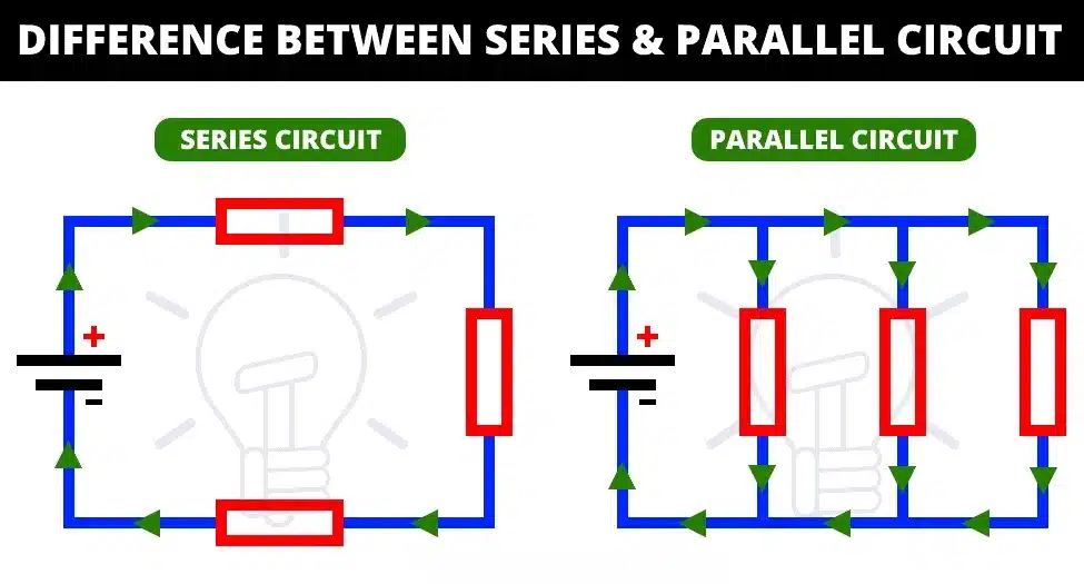
Series vs. Parallel Circuits
- Series: Components connected end-to-end. Current flows in one path.
- Parallel: Components connected side-by-side. Current has multiple paths.
💡 Example: Christmas lights in series go out if one bulb breaks. Parallel connections prevent that problem.
Step-by-Step: How to Read a Simple Circuit Diagram
- Identify the power source (battery or plug).
- Follow the flow of current from positive to negative.
- Recognize each symbol (resistor, capacitor, diode, etc.).
- Check connections (series or parallel).
- Think about function: What is this circuit supposed to do?
💡 Example Walkthrough:
Imagine a diagram with a battery connected to a resistor, then to an LED, and back to the battery. The function is simple: the resistor protects the LED, and the LED lights up when powered.
Tips for Beginners Learning Circuit Diagrams
- Start with simple diagrams like an LED circuit or a basic switch.
- Memorize symbols gradually (flashcards can help).
- Redraw circuits by hand to practice recognition.
- Use simulation software like Tinkercad or EveryCircuit to test diagrams virtually.
- Cross-reference with real components to connect the symbol to its physical appearance.
Common Mistakes Beginners Make
- Confusing symbols (e.g., capacitor vs. battery).
- Missing junction dots where wires connect.
- Forgetting the current direction (from positive to negative).
- Ignoring resistor values can cause LEDs or other components to burn out.
Practice Makes Perfect
The more diagrams you study, the easier it gets. Start by reading very basic ones, then move toward more complex projects. Over time, you’ll be able to glance at a schematic and instantly understand the flow.
Conclusion
Learning how to read circuit diagrams is like unlocking the language of electronics. With practice, what once looked like confusing symbols will turn into a clear story of how electricity moves through a system.
👉 If you’ve already learned about electronic components, now is the time to put that knowledge into action by practicing with circuit diagrams. Start small, stay consistent, and soon you’ll be ready to design your own!