Overview
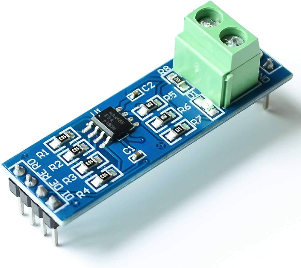
The TTL To RS-485 Converter Module Board (MAX485) provides a simple, reliable interface between TTL-level UARTs (5V or 3.3V) and RS-485 differential buses. RS-485 is the preferred standard for long-distance, multi-drop communication in industrial automation, building control and IoT networks. This module uses the MAX485 low-power transceiver to deliver robust data transmission over extended distances while keeping power consumption low.
Key Features
- Efficient TTL to RS-485 conversion using the MAX485 chip
- Supports long-range communication up to 1200 meters (typical RS-485 capability)
- Low power consumption, suitable for battery-powered or energy-conscious systems
- Multi-drop support to connect multiple devices on a single RS-485 bus
- Compatible with 5V and 3.3V TTL logic, ideal for Arduino, Raspberry Pi and other microcontrollers
- Industrial-grade reliability for noisy electrical environments
Technical Specifications
- Transceiver chip: MAX485 low-power RS-485/RS-422 transceiver
- Input logic: TTL/CMOS 5V or 3.3V compatible
- Communication standard: RS-485 differential A/B pair
- Maximum practical range: up to 1200 meters (line and environment dependent)
- Data rates: supports typical UART speeds for industrial communications (refer to MAX485 datasheet for max bitrate)
- Power consumption: low-power design suitable for continuous operation
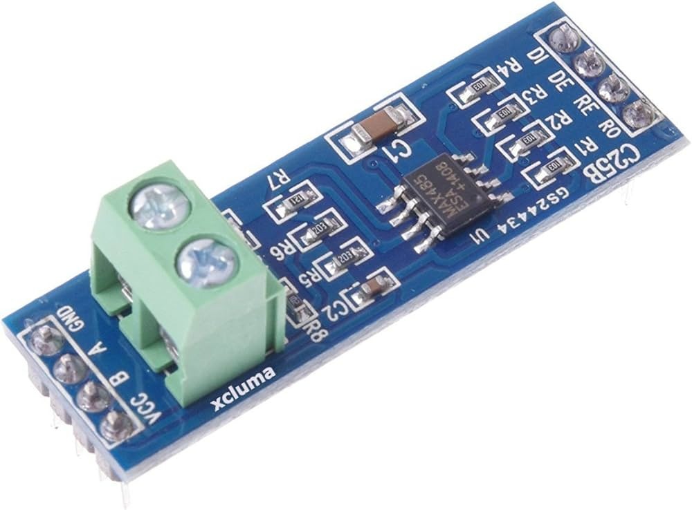
Pinout and Wiring (Typical)
Most MAX485 TTL-to-RS485 modules expose the following pins or terminals. Verify the silkscreen or product documentation for your specific board before wiring.
- VCC – Module power input (5V or 3.3V depending on board/version)
- GND – Ground reference
- DI (TX) – TTL serial data input (driver input)
- RO (RX) – TTL serial data output (receiver output)
- DE – Driver enable (usually tied with RE for direction control)
- RE – Receiver enable (active low on many boards)
- A / B – RS-485 differential bus lines (connect to other RS-485 devices)
Basic Arduino Connection
- Connect VCC to 5V (or 3.3V if the module supports it), and GND to Arduino GND
- Connect Arduino TX to module DI, and Arduino RX to module RO
- Control DE/RE to switch between send and receive, or tie DE and RE together and drive from a digital pin
- Connect A and B to the RS-485 bus (observe polarity across devices)
Compatibility and Applications
This module is ideal for projects that require long-distance, stable serial communication from microcontrollers and single-board computers. Typical applications include:
- Industrial automation: PLCs, motor controllers, sensors and factory equipment
- Building automation: HVAC control, access control and lighting systems
- IoT and remote monitoring: sensor networks, telemetry and agricultural monitoring
- Communication systems: multi-node serial networks and remote controllers
Integration Tips for Reliable RS-485 Communication
- Use proper termination resistors (typically 120 ohm) at both ends of the RS-485 bus to prevent reflections
- Use twisted-pair cable for A/B lines and keep cable runs away from high-voltage sources to reduce noise
- If multiple nodes drive the bus, ensure only one driver is enabled at a time using DE/RE control
- Consider biasing resistors or fail-safe resistors if your network can be idle for extended periods
- Verify voltage compatibility (5V vs 3.3V) before connecting to your controller to avoid damage
Why Choose the TTL To RS-485 Converter Module Board (MAX485)?
Whether building an industrial control network, a multi-node IoT system or a remote monitoring solution, this MAX485-based module provides a compact, low-power and cost-effective way to extend TTL serial links to RS-485 networks. Its wide compatibility and robust design make it a go-to choice for engineers and hobbyists who need reliable long-range communication.
Note: Images are for Illustration Purposes Only


Reviews
There are no reviews yet