
TCRT5000 IR Line Tracking Sensor Module Overview
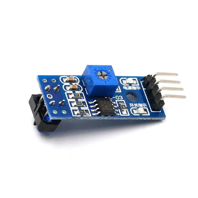
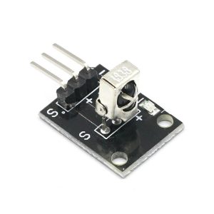
The TCRT5000 IR Line Tracking Sensor Module is a compact infrared reflectance sensor designed to detect black and white surfaces quickly and reliably. It combines an IR emitter and phototransistor in a single package and is commonly used in line-following robots, edge detection, position sensing, and general proximity detection in automation projects.
Why choose the TCRT5000 sensor?
- Fast and reliable reflectance detection for dark and light surfaces
- Easy integration with microcontrollers such as Arduino, Raspberry Pi, AVR, and PIC
- Adjustable threshold and both analog and digital outputs for flexible designs
- Low power consumption and compact footprint for space-constrained projects
Key Features
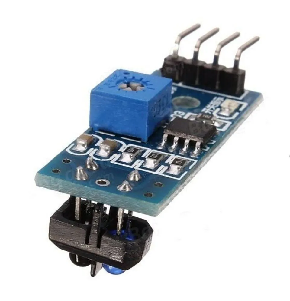
- Integrated infrared emitter and phototransistor (TCRT5000 package)
- Detection range: typically 0.2 cm to 15 cm (optimal < 12 mm)
- Onboard potentiometer to adjust sensitivity and switching threshold
- Dual outputs: Analog Output (AO) for variable readings and Digital Output (DO) for threshold switching
- Onboard comparator for clean digital signals and stable switching
- Indicator LED to show detection status at a glance
- Operating voltage: 3.3V to 5V, compatible with popular development boards
- Compact, durable, and energy-efficient design
Technical Specifications
- Sensor IC: TCRT5000 (IR emitter + phototransistor)
- Analog Output: AO (voltage proportional to reflected IR)
- Digital Output: DO (TTL level after comparator)
- Operating Voltage: 3.3V to 5V DC
- Typical Detection Range: 0.2 cm to 15 cm (optimal under 12 mm)
- Indicator: onboard LED
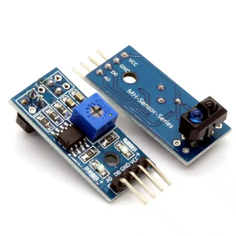
- Connections: 3-pin or 4-pin header depending on module variant (VCC, GND, AO, DO)
Wiring and Integration
Basic connections
- VCC: 3.3V to 5V power supply
- GND: Ground
- AO: Analog output to ADC pin on microcontroller (optional)
- DO: Digital output to digital input pin on microcontroller (optional)
Arduino example wiring
- Connect VCC to 5V (or 3.3V) on Arduino
- Connect GND to Arduino GND
- Connect AO to an analog pin (A0) to read reflectance values
- Connect DO to a digital pin (D2) to use threshold switching
- Use the onboard potentiometer to set the DO switching threshold
Raspberry Pi integration
- Use 3.3V VCC when connecting to Raspberry Pi 3.3V GPIO to avoid voltage issues
- Connect AO to an external ADC if analog readings are required (Pi has no built-in ADC)
- Connect DO directly to a GPIO pin for digital detection (use proper pull-up or pull-down configuration)
Calibration and Mounting Tips
- Mount the sensor 5 to 12 mm from the surface for optimal detection sensitivity
- Adjust the onboard potentiometer while monitoring AO or the indicator LED until the module reliably distinguishes black from white surfaces
- Use shielding or a small tube around the sensor to reduce ambient light interference in bright environments
- For multi-sensor arrays in line-following robots, calibrate each sensor individually under the same lighting conditions
Typical Applications
- Line-following robots and educational robotics kits
- Edge detection and position sensing in mobile robots
- Obstacle proximity sensing for lightweight automation
- DIY electronics projects, STEM learning, and prototyping
Quick Start
- Wire VCC and GND to your controller supply
- Use AO to get raw reflectance values and DO for threshold events
- Turn the potentiometer to tune detection threshold for your surface and lighting
- Test with black and white reference samples to confirm reliable switching
Note: Images are for illustration purposes only.


Reviews
There are no reviews yet