Overview: Reliable 8-Channel Relay Control
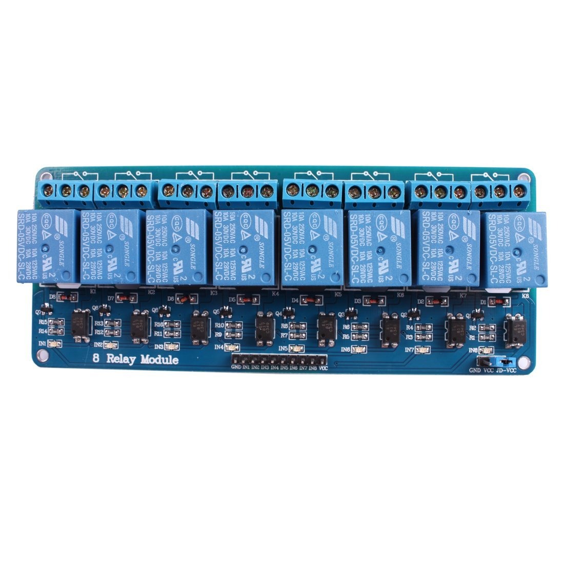
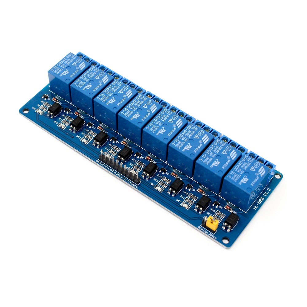
The Relay Module (8-Channel) is a compact relay board that lets you switch eight independent high-current loads using low-voltage digital signals. Designed for hobbyist, maker and light industrial applications, this 8-channel relay module simplifies integration with microcontrollers like Arduino, Raspberry Pi and ESP32, as well as PLCs and automation systems.
Key Features of this 8-channel relay module
- Eight individual mechanical relay channels for independent switching
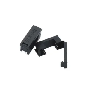
- Jumper-selectable JD-VCC / VCC isolation to separate relay coils from logic power
- Per-channel LED indicators for visual status and troubleshooting
- TTL compatible trigger inputs (typically 3.3V and 5V friendly)
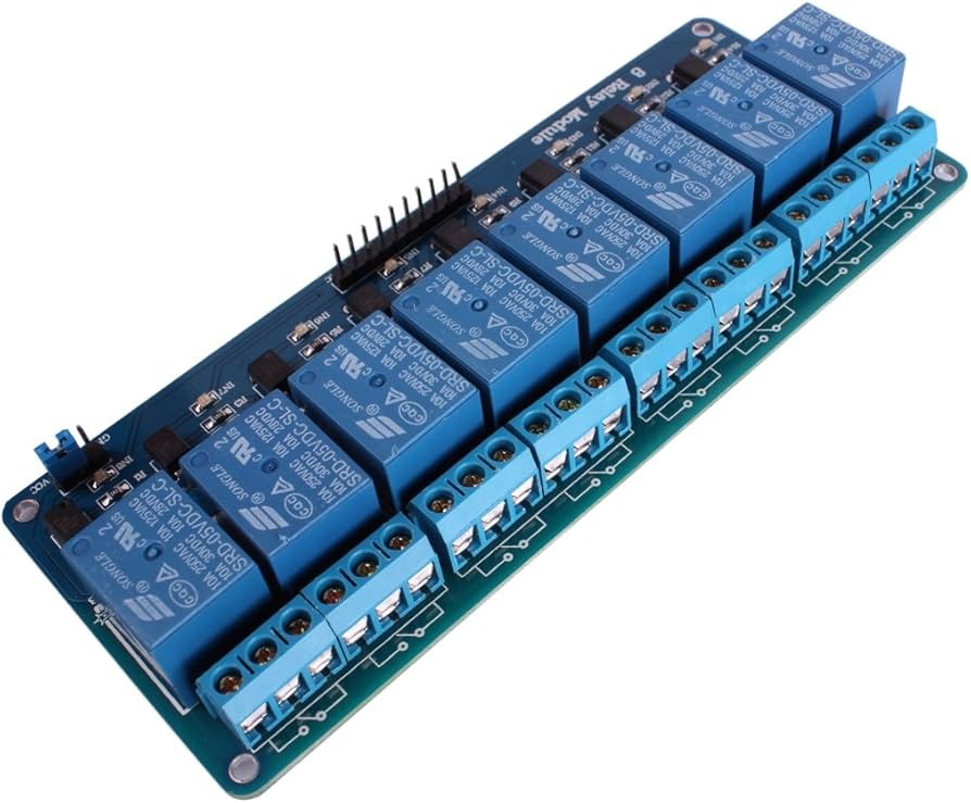
- Choice of screw terminals or header pins for load and signal wiring
- Compact PCB with mounting holes for quick installation in enclosures
- Typical relay contact rating up to 10A per channel; confirm relay model/datasheet for exact limits
Why choose this 8-channel relay board
This relay module converts low-current digital outputs into switched high-current outputs so you can control lights, pumps, heaters, motors and other AC or DC loads. Jumper-selectable isolation and status LEDs make it a safe and convenient choice for prototyping and production use.
Benefits
- Expand a microcontroller’s output capacity without redesigning hardware
- Protect your logic controller by isolating relay coil power from TTL signals
- Simplify wiring and troubleshooting with labeled terminals and LED feedback
- Mount easily in project boxes or cabinets using included PCB mounting holes
Common applications
- Home automation: remote or scheduled control of lights and appliances
- Robotics and mechatronics: switching motors, solenoids and actuators
- Industrial control: interface low-voltage controllers to higher-voltage loads
- Education and prototyping: teach switching, control logic and electrical safety
Quick wiring guide and examples
Basic single-supply Arduino wiring:
- Connect VCC to the Arduino 5V pin and GND to ground.
- Connect IN1–IN8 to digital pins on your microcontroller (use digitalWrite or similar to toggle).
- With the isolation jumper fitted, the board uses the same supply for logic and relay coils.
Using JD-VCC isolation (recommended for noisy or high-current loads):
- Remove the JD-VCC jumper.
- Supply JD-VCC with a separate power source for the relay coils (for example, a dedicated 5V supply) and keep VCC as the logic power for the microcontroller.
- Connect grounds if required by your control logic; follow module documentation to ensure correct wiring for your configuration.
Notes:
- Some modules use active-low inputs. Verify whether your board triggers on LOW or HIGH and invert logic in software if needed.
- Use the onboard LEDs to confirm channel activation during setup and debugging.
Safety, protection and best practices
- Verify the relay contact rating before switching mains voltage or heavy inductive loads.
- Use fuses, snubbers, flyback diodes or TVS devices when switching motors, solenoids or other inductive loads to protect contacts and driver circuitry.
- Follow local electrical codes when wiring mains AC loads and keep mains wiring insulated and secured.
- Disconnect power before making wiring changes or modifications.
Specifications
- Product: Relay Module (8-Channel)
- Relay type: mechanical relays (verify exact relay model in datasheet)
- Typical contact rating: up to 10A per channel (confirm in datasheet)
- Logic trigger: TTL compatible, typically supports 3.3V and 5V
- Connections: IN1–IN8, VCC, GND, JD-VCC (if applicable), screw terminals for loads
- Mounting: PCB with mounting holes
Ordering, alternatives and support
Order the Relay Module (8-Channel) for multi-output control in automation, IoT and maker projects. If you require a different contact rating, a specific relay model, or a solid-state relay alternative, consult our catalog or contact support for custom configurations and volume pricing.
Troubleshooting and FAQ
- Q: Module does not trigger from Raspberry Pi GPIO. A: Check whether inputs are active-low or active-high, ensure logic voltage compatibility (3.3V), and confirm grounding if using separate JD-VCC supply.
- Q: Relays chatter or reset the controller. A: Ensure proper isolation, use a dedicated relay supply for JD-VCC, and add flyback/snubber protection for inductive loads.
- Q: Where can I find exact relay limits? A: Check the relay model printed on the board or the product datasheet for exact contact ratings and specifications.


Reviews
There are no reviews yet