
MAX232 RS-232 to TTL Converter Overview
The MAX232 is a widely used RS-232 to TTL level converter IC designed to provide reliable serial communication between RS-232 devices and TTL/CMOS logic devices such as microcontrollers, development boards, modems, GPS modules, and other serial peripherals. The IC generates RS-232 compatible voltages internally from a single +5V supply and provides two drivers and two receivers for full-duplex communication.
Key Features
- Converts RS-232 signal levels to TTL/CMOS levels and vice versa
- Two receivers (R1, R2) and two drivers (T1, T2) for dual channel full-duplex use
- Operates from a single +5V supply using internal charge pump circuitry
- Requires four external capacitors (typically 1 µF) for the charge pump
- Low supply current (typical 8 mA) and support for data rates up to 120 kbps
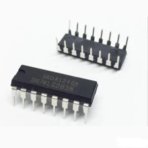
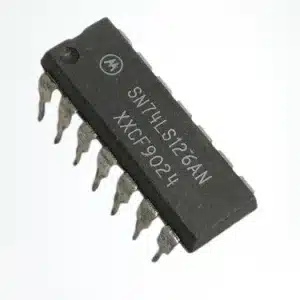
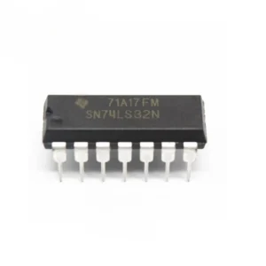
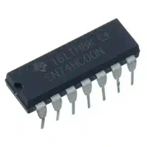
- Standard 16-pin DIP package for easy prototyping on breadboards
- TTL-compatible outputs for direct connection to microcontrollers and logic circuits
Functional Description
- Transmitters (T1, T2): Convert TTL/CMOS logic levels (0V to 5V) to RS-232 voltage levels (approximately ±10V) suitable for driving RS-232 inputs.
- Receivers (R1, R2): Accept RS-232 input signals (±3V and beyond) and translate them to TTL logic levels for microcontrollers and logic circuits.
- Charge Pump: Internal charge pump and four external capacitors generate the required RS-232 voltages from a single +5V supply, removing the need for negative voltage rails.
- Bi-directional Data: The combination of drivers and receivers supports bi-directional, full-duplex serial communication between RS-232 devices and TTL devices.
Typical Applications
- Serial communication between PCs and microcontrollers (Arduino, PIC, AVR, ARM, Raspberry Pi via UART)
- Interfacing modems, GPS, GSM modules, and serial sensors to TTL logic
- Serial console interfaces for embedded systems and routers
- Data logging, diagnostic equipment, instrumentation, and industrial automation systems
Benefits of Using MAX232
- Simplifies level shifting between RS-232 and TTL without dual power rails
- Reduces component count by integrating charge pump circuitry
- Easy to prototype with standard 16-pin DIP package
- Reliable signal integrity and good noise immunity for robust data links
Specifications
- Type: RS-232 to TTL converter IC
- Logic family: TTL/CMOS compatible
- Supply voltage (VCC): 4.5V to 5.5V
- Typical supply current: 8 mA
- Data rate: Up to 120 kbps
- Operating temperature range: 0°C to +70°C
- RS-232 output voltage: approximately ±10V
- TTL output voltage: 0V to 5V
- Package: 16-pin DIP
Pinout and Package
The MAX232 is commonly available in a 16-pin DIP package that is breadboard friendly. Typical pinout includes two driver outputs, two receiver inputs, VCC, ground, and four capacitor connections for the internal charge pump. Consult the device datasheet for the exact pin numbering and recommended capacitor values.
Typical Connection and Wiring
- Connect VCC to +5V and GND to system ground.
- Place four external capacitors (commonly 1 µF each) between the charge pump pins as recommended in the datasheet.
- Connect TTL UART TX of the microcontroller to a MAX232 transmitter input; connect the corresponding RS-232 output to the RS-232 device.
- Connect RS-232 input from the external device to a MAX232 receiver input; the MAX232 TTL output goes to the microcontroller RX.
- Verify ground reference between devices for reliable communication.
Design Notes and Tips
- Use the capacitor values recommended in the datasheet for stable charge pump operation, typically 1 µF to 10 µF depending on variant.
- Keep traces for RS-232 signals short and add filtering or transient protection if exposed to noisy environments.
- For 3.3V systems, choose a level translator or variant compatible with lower VCC; the MAX232 requires ~5V operation.
- Refer to the full manufacturer datasheet for absolute maximum ratings, timing diagrams, and thermal information.
Note: Images are for illustration purposes only.


Reviews
There are no reviews yet