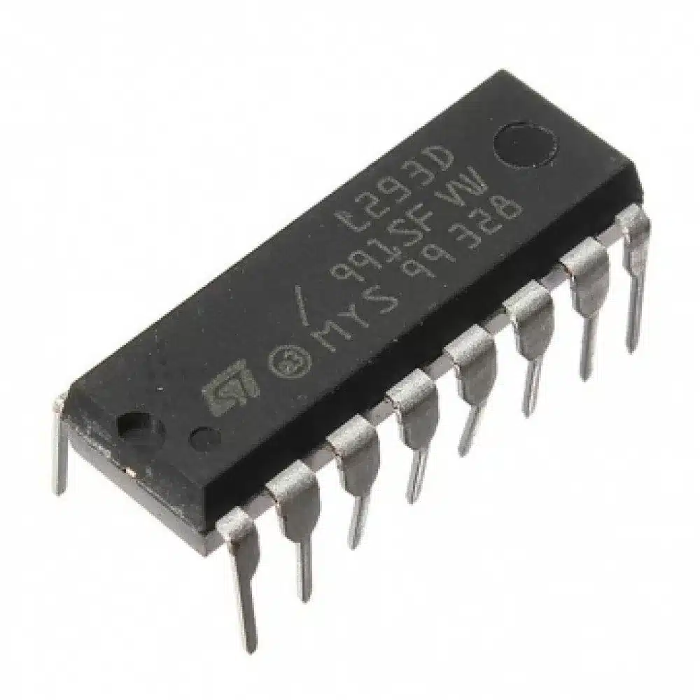
Overview: L293D Dual H-Bridge Motor Driver IC
The L293D is a widely used dual H-Bridge motor driver IC designed for robotics, automation, and embedded electronics projects. It enables bidirectional control of two DC motors or one stepper motor using simple logic inputs from microcontrollers such as Arduino, Raspberry Pi, or PIC. Its compact 16-pin DIP package makes it ideal for breadboard prototyping and small PCB designs.
Why choose the L293D for motor control
- Dual H-Bridge architecture to control two motors independently or one stepper motor.
- TTL and CMOS compatible inputs for easy interfacing with microcontrollers and logic circuits.
- Internal clamp diodes provide back EMF protection for safer motor switching.
Key Features
- Dual H-Bridge motor driver IC.
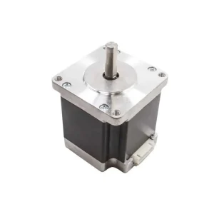
- Controls 2 DC motors or 1 stepper motor with independent speed and direction.
- Motor direction: forward and reverse.
- Motor speed control via PWM signals from microcontrollers.
- Wide supply voltage range: 4.5V to 36V.
- Output current: up to 600mA per channel, 1.2A peak.
- Internal clamp diodes for back EMF protection.
- TTL and CMOS compatible logic inputs.
- Compact 16-pin DIP package for breadboards and prototyping.
Typical Applications
- Robotics projects and small robot motor drivers.
- Stepper motor control for simple positioning systems.
- Arduino and Raspberry Pi motor control projects.
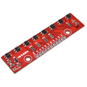
- Line follower robots, obstacle-avoiding robots, and robotic arms.
- Automation and mechatronics prototypes.
- General electromechanical power control for hobby and educational use.
Specifications
- Package: 16-pin DIP
- Supply voltage (motor): 4.5V to 36V
- Logic supply: TTL/CMOS compatible (use appropriate Vcc for logic)
- Output current: up to 600mA per channel, 1.2A peak
- Protection: internal clamp diodes for back EMF
Compatibility and Interfacing
The L293D is commonly used with microcontrollers such as Arduino, Raspberry Pi (via level shifting for 3.3V logic), and PIC. Use PWM-capable pins on your controller for speed control and digital outputs for direction. Logic inputs accept standard TTL/CMOS levels.
Wiring Tips and Best Practices
- Use a separate motor power supply when possible to avoid noise on the logic supply. Connect common ground between motor and logic supplies.
- Add decoupling capacitors near the IC to reduce supply transients and improve stability.
- Observe the 600mA continuous limit per channel; for higher continuous currents use a dedicated motor driver or add external current limiting and adequate heat dissipation.
- Place a flyback diode or rely on the IC’s internal clamp diodes and verify their suitability for your motor’s characteristics.
- Test motors at lower voltages first and monitor temperature during extended operation.
Getting Started
- Connect logic Vcc and motor Vcc to appropriate supplies (observe voltage limits).
- Common the grounds of logic and motor supplies.
- Wire motor terminals to the output pins and microcontroller control pins to the input pins.
- Use PWM signals for speed control and toggle direction pins for forward/reverse operation.
Notes
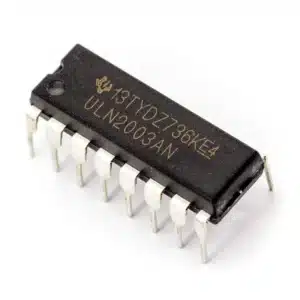
Images are for illustration purposes only. Verify pinout and connections against the L293D datasheet for your specific PCB or module variant before powering the circuit.


Reviews
There are no reviews yet