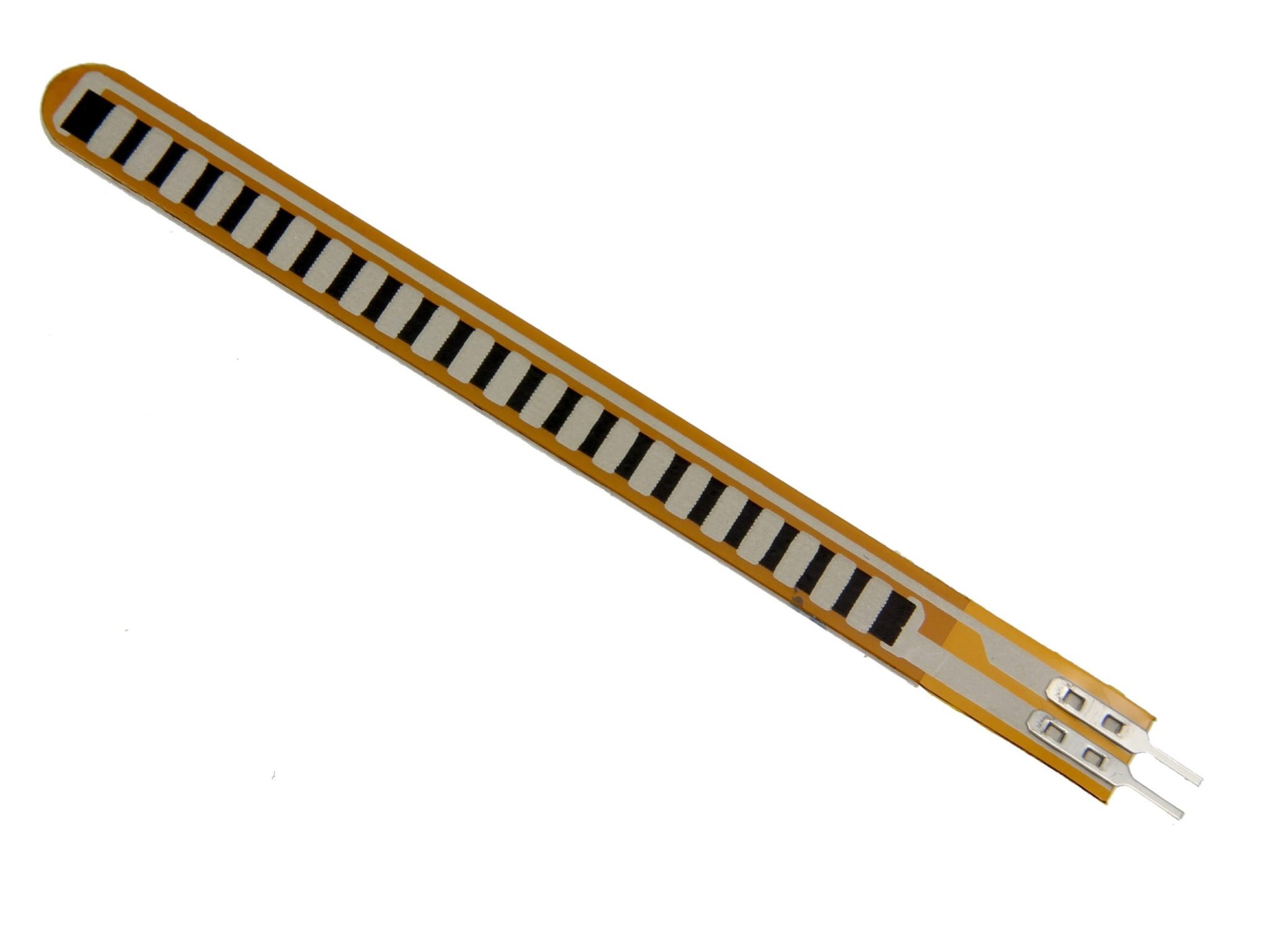
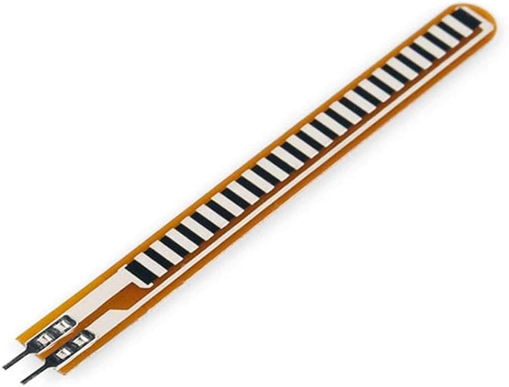
Overview – Flex Sensor (2.2 Inch)
The Flex Sensor (2.2 Inch) is a high-sensitivity bending sensor that converts physical flex into a measurable change in resistance. Designed for reliable, repeatable measurements, this compact sensor is ideal for wearable electronics, robotics, medical motion monitoring, gaming input and interactive musical controllers. Its simple resistance-based analog output makes it easy to integrate with Arduino, Raspberry Pi analog-to-digital converters and other microcontrollers.
Key Features
- High sensitivity to bending in one direction for accurate motion detection
- Durable construction to withstand repeated flex cycles
- Simple analog output – reads as resistance change across a 2-pin connector
- Compact 2.2-inch (55.88 mm) length – fits small or wearable projects
- Wide operating temperature range for indoor and outdoor use
Specifications
- Length: 2.2 inches (55.88 mm)
- Thickness: Approximately 0.43 mm
- Resistance Range: ~10 KΩ (flat) to 20 KΩ – 30 KΩ (bent to 180 degrees)
- Operating Voltage: 0 V to 5 V (reads as part of a voltage divider)
- Temperature Range: -35°C to +80°C
- Connector Type: 2-pin header
Applications
- Wearable Technology: Finger, wrist, elbow or knee motion sensing for gesture control and fitness trackers
- Robotics: Joint angle sensing, gripper position feedback, and arm motion monitoring
- Medical Devices: Prosthetics, rehabilitation tools and physical therapy motion monitoring
- Gaming and Controllers: Motion-sensitive inputs for interactive gaming and custom controllers
- Musical Instruments: Motion-triggered effects and expressive control in electronic instruments
Integration and Wiring
The Flex Sensor (2.2 Inch) outputs a variable resistance. To read it with most microcontrollers, use it as part of a voltage divider. The sensor and a fixed resistor form two legs of the divider and the midpoint is connected to an analog input.
Recommended Voltage Divider
- Use a fixed resistor near the sensor’s flat resistance – typically a 10 KΩ resistor works well.
- Power the divider from 3.3 V or 5 V depending on your microcontroller’s ADC range. Do not exceed 5 V.
- Connect sensor to Vcc and the fixed resistor to ground, then read the midpoint with an analog input.
Reading with Arduino
Example wiring and read approach:
// Connect sensor and 10K resistor as a voltage divider
// Sensor to 5V -> midpoint -> A0 -> resistor to GND
int sensorPin = A0;
void setup() {
  Serial.begin(9600);
}
void loop() {
  int val = analogRead(sensorPin);
  Serial.println(val);
  delay(200);
}
Mounting, Calibration and Tips
- Mount the sensor flat at one end and allow free flex at the other for consistent readings.
- Avoid sharp bends and creasing – the sensor is durable but sharp folds reduce life and accuracy.
- Calibrate by recording ADC values at flat and at known bend angles to map resistance to degrees.
- Use filtering or averaging in software to smooth out jitter in analog readings.
- Protect contacts from moisture and abrasion in wearable or outdoor applications.
Why Choose the Flex Sensor (2.2 Inch)
Its compact size, reliable resistance-based output and robust construction make the Flex Sensor (2.2 Inch) a practical choice for prototypes and production: from quick Arduino experiments to embedded wearable systems and medical monitoring devices. The 2-pin header and standard resistance range simplify integration and troubleshooting.
Note: Images are for illustration purposes only.


Reviews
There are no reviews yet