ACS712 20A Hall Effect Current Sensor Module — Overview
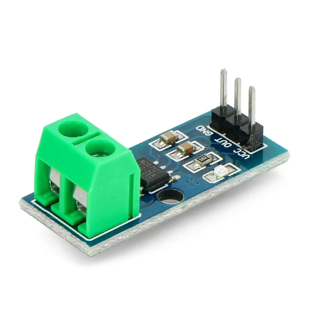
The ACS712 20A Hall Effect Current Sensor Module provides accurate, isolated measurement of AC and DC currents up to ±20A. Built around the proven ACS712 Hall effect IC, it outputs an analog voltage proportional to the sensed current, making it ideal for monitoring, control and protection systems in embedded projects and industrial applications.
Key Features
- Measures AC and DC currents up to ±20A
- Output sensitivity: 100 mV/A (approximate)
- Galvanic isolation between the measured conductor and the microcontroller
- Low noise, reliable analog output suitable for ADC sampling
- Operating voltage: 5V DC
- Compact, robust PCB for easy mounting
- Compatible with Arduino, ESP32, STM32, Raspberry Pi and other microcontrollers
Technical Specifications
- Sensor IC: ACS712 Hall effect
- Measurement range: ±20A
- Sensitivity: 100 mV per ampere (100 mV/A)
- Typical zero-current output: VCC / 2 (≈ 2.5V at 5V supply)
- Supply voltage: 5V DC
- Analog output: voltage proportional to current (swing ≈ ±2.0V around mid-point at ±20A)
- Recommended connections: single conductor through sensor opening or PCB shunt path
Applications
- Power and energy consumption monitoring
- Battery management systems and charging circuits
- Motor control, robotics and speed regulation
- Over-current detection and protection circuits
- Renewable energy systems, inverters and chargers
- DIY electronics, makers and educational projects
Wiring and Interfacing
Connect the module VCC to 5V, GND to system ground and the analog output (Vout) to an ADC input on your microcontroller. The ACS712 produces a mid-point voltage at zero current (usually VCC/2). When current flows, the output shifts above or below that mid-point by roughly 100 mV per ampere.
Quick wiring summary
- VCC: 5V DC
- GND: Ground
- OUT: Analog voltage to ADC (centered at ~2.5V for 0A)
- Current path: Pass the measured conductor through the module sensing path
Tips for reliable readings
- Add a 0.1 uF decoupling capacitor between VCC and GND close to the module to reduce supply noise.
- Apply a small RC or software filter to smooth high-frequency noise and transients.
- Use ADC averaging or oversampling to improve effective resolution when measuring small currents.
- Remember the output is centered at VCC/2; subtract that offset before converting to amps using the 100 mV/A sensitivity.
Example: Converting ADC reading to current (concept)
1. Read ADC value and convert to voltage (Vout). 2. Subtract VCC/2 to get sensor delta. 3. Current (A) = (Vout – VCC/2) / 0.100.
Installation and Safety
- Ensure correct wiring and secure mounting to avoid mechanical stress on conductors.
- Although the sensor provides galvanic isolation, follow standard safety practices when working with high currents and mains voltages.
- Do not exceed the ±20A rating to avoid overheating or damaging the module.
Why choose the ACS712 20A Module
This module combines a simple analog interface with safe Hall effect isolation, making it perfect for makers and engineers who need reliable current measurement on platforms such as Arduino, ESP32, STM32 and Raspberry Pi. Its compact form factor and low-noise performance allow straightforward integration into monitoring, motor control and automation systems.
Note: Images are for Illustration Purposes Only.


Reviews
There are no reviews yet