Overview
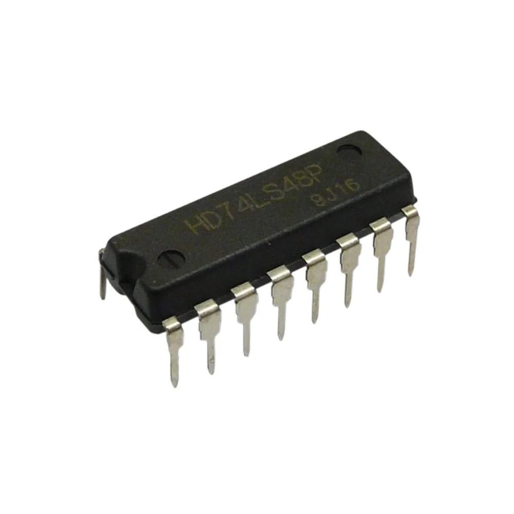
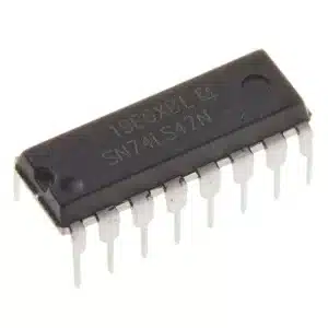
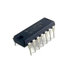
The 7448 BCD to 7-Segment Decoder/Driver IC is a TTL logic device that converts 4-bit Binary Coded Decimal (BCD) inputs into the proper segment outputs to drive standard 7-segment LED displays. Supplied in a 16-pin Dual In-Line Package (DIP), the 7448 is breadboard friendly and well suited to educational projects, hobby electronics, and industrial numeric display applications.
Key Features
- BCD to 7-segment decoding: Converts A, B, C, D inputs into segment outputs a through g
- Designed for LED displays: Compatible with standard common anode 7-segment indicators (use current-limiting resistors)
- TTL logic family: Standard TTL voltage levels for easy interfacing with legacy and modern TTL-compatible systems
- Control inputs: Lamp test, blanking input and ripple blanking for leading zero suppression and diagnostics
- Package: 16-pin DIP for easy prototyping and through-hole PCB assembly
Technical Specifications
- IC Type: BCD to 7-Segment Decoder/Driver
- IC Number: 7448
- Logic Family: TTL
- Package Type: DIP (Dual In-Line Package), 16 pins
- Input Type: 4-bit BCD (A, B, C, D)
- Output Type: 7-segment outputs (a through g)
- Operating Voltage: 5 V typical
- Operating Temperature: Standard commercial range
Typical Applications
- Digital clocks and timers
- Counters and frequency displays
- Numeric display systems and instrumentation
- Arduino and microcontroller display interfacing
- Educational electronics and logic demonstrations
Advantages
- Simplifies driving 7-segment displays by handling segment decoding internally
- Reduces external component count compared to discrete decoding circuits
- Reliable TTL performance and predictable timing
- Easy integration into prototypes and final designs using DIP footprint
Usage Notes and Typical Connection Tips
- Use appropriate current-limiting resistors (one per segment) when connecting LED segments to prevent damage.
- The 7448 is intended for common anode displays; confirm display type before wiring.
- Ensure a stable 5 V supply and correct power polarity to avoid IC damage.
- Use lamp test to illuminate all segments for quick verification of display and wiring.
- Blanking and ripple blanking inputs allow suppression of leading zeros in multi-digit displays when chaining multiple decoders.
Safety and Handling
- Observe ESD precautions when handling the IC to protect the internal gates.
- Always power down circuits before inserting or removing the IC from a socket or breadboard.
- Verify wiring and resistor values before applying power to prevent excessive LED current.
Note: Images are for Illustration Purposes Only. Actual IC manufacturer marking and appearance may vary slightly.


Reviews
There are no reviews yet