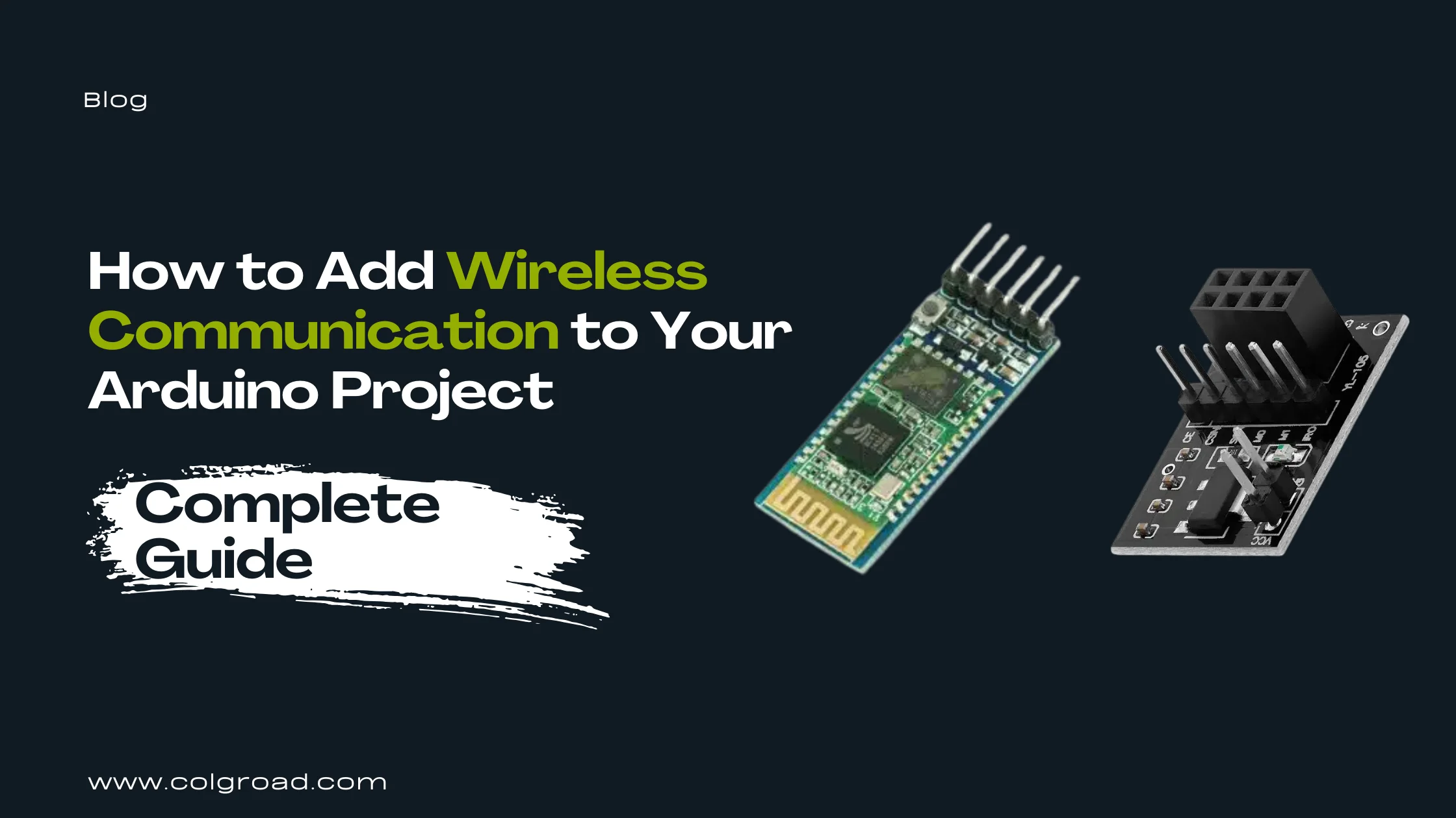
Wires limit what your projects can do. Whether you want to control a robot from your phone, send sensor data between two Arduinos across a room, track a vehicle's location, or receive SMS alerts from a remote device, wireless communication modules make it possible. This guide covers the most practical wireless options available for Arduino projects, helping you choose the right module for your specific needs.
Understanding Wireless Communication Options
Before selecting a wireless module, you need to understand what each technology offers and where it works best. The choice depends on several factors: the distance between devices, whether you need internet connectivity, power consumption requirements, and the type of data you want to transmit.
Each wireless technology operates differently. Bluetooth creates direct connections between nearby devices like your phone and Arduino. RF (Radio Frequency) modules enable communication between multiple Arduinos without requiring phones or internet. GPS modules receive satellite signals to determine location coordinates. GSM modules use cellular networks to send SMS messages and make calls from anywhere with mobile coverage.
| Technology | Range | Best For | Requires |
|---|---|---|---|
| Bluetooth (HC-05) | 10 meters | Phone control, short-range data | Paired device (phone/PC) |
| RF (NRF24L01) | 100+ meters | Arduino-to-Arduino, sensor networks | Two or more modules |
| GPS (NEO-6M) | Global (satellite) | Location tracking, navigation | Clear sky view |
| GSM (SIM800L) | Cellular coverage | SMS alerts, remote monitoring | SIM card with credit |
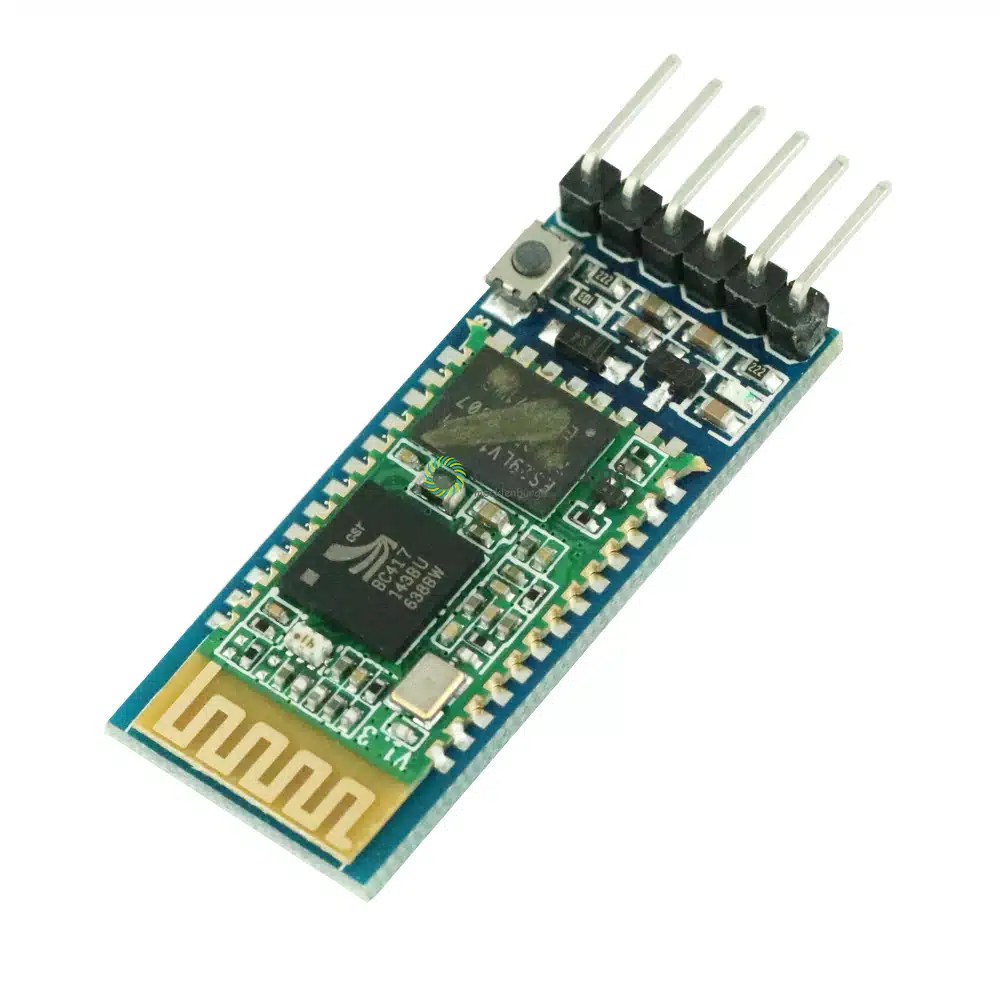
Bluetooth Communication with HC-05
The HC-05 Bluetooth module remains the most popular choice for connecting Arduino projects to smartphones. It creates a wireless serial connection, meaning any code that works with wired serial communication works wirelessly with minimal changes. This simplicity makes it the recommended starting point for anyone new to wireless Arduino projects.
How Bluetooth Communication Works
The HC-05 acts as a wireless serial port. Your Arduino sends data through its TX pin to the module, which transmits it over Bluetooth to a paired device. The paired device (usually a smartphone) receives this data and can send commands back. From the Arduino's perspective, it works exactly like communicating through a USB cable.
The module supports both Master and Slave modes. In Slave mode (default), it waits for other devices to connect. In Master mode, it actively seeks and connects to other Bluetooth devices. Most phone-controlled projects use Slave mode since your phone initiates the connection.
Smartphone-controlled robots and cars. Home automation control panels. Wireless sensor data display on phone apps. Remote debugging and monitoring. Bluetooth-enabled door locks. Wireless game controllers.
Basic Wiring
Connect VCC to 5V on Arduino, GND to ground, TX on module to RX on Arduino (through voltage divider), and RX on module to TX on Arduino. The HC-05 logic levels are 3.3V, so using a voltage divider on the RX line protects the module when receiving data from a 5V Arduino.
#include <SoftwareSerial.h>
SoftwareSerial BTSerial(10, 11); // RX, TX
void setup() {
pinMode(13, OUTPUT);
BTSerial.begin(9600);
}
void loop() {
if (BTSerial.available()) {
char command = BTSerial.read();
if (command == '1') digitalWrite(13, HIGH);
if (command == '0') digitalWrite(13, LOW);
}
}
Download a Bluetooth terminal app on your Android phone (Serial Bluetooth Terminal works well). Pair your phone with the HC-05 module using password 1234. Open the app, connect to HC-05, and send characters to test communication. The onboard LED blinks rapidly when searching and blinks slowly when connected.
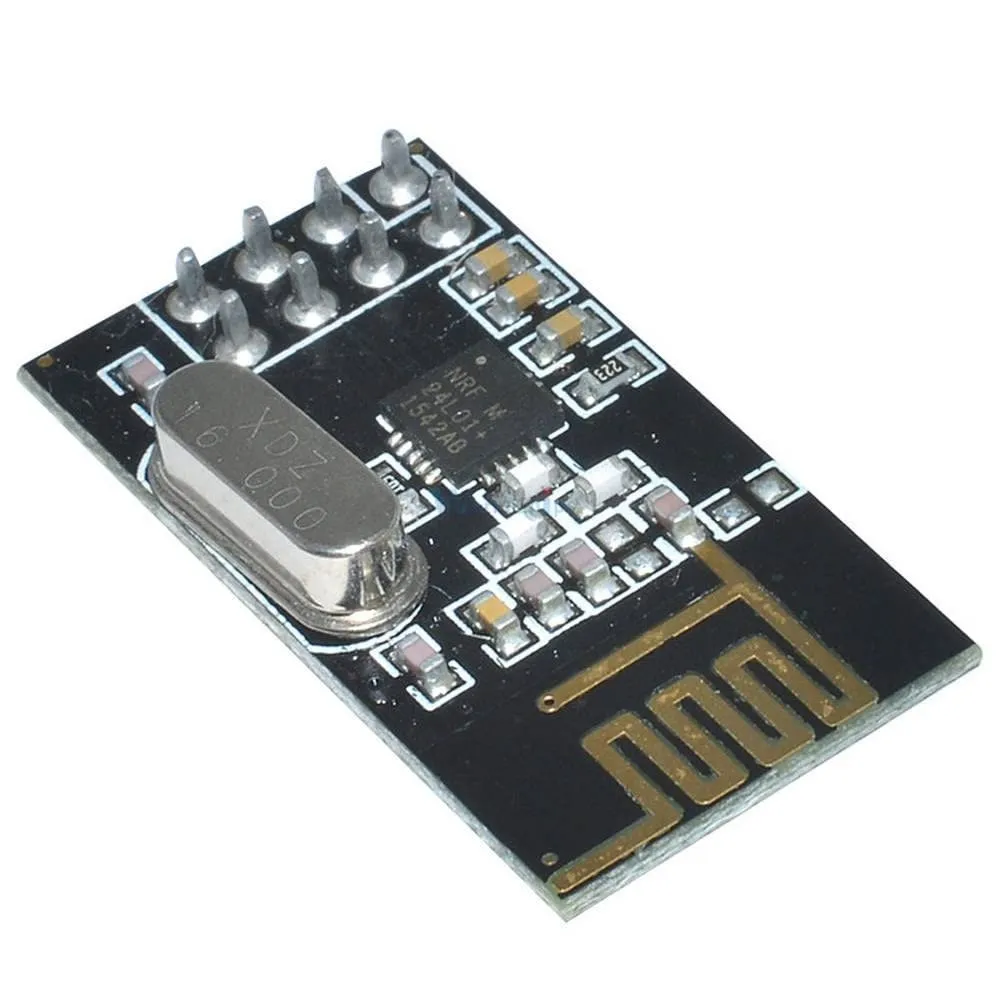
RF Communication with NRF24L01
When your project requires communication between two or more Arduino boards without involving phones or internet, the NRF24L01 module provides an excellent solution. These 2.4GHz transceivers can both send and receive data, enabling true two-way communication between multiple devices.
Why Choose NRF24L01
The NRF24L01 offers several advantages over simpler RF modules. It operates at 2.4GHz with 125 selectable channels, reducing interference issues. Each module can communicate with up to six other modules simultaneously. Built-in error checking and automatic retransmission ensure reliable data delivery. Power consumption is remarkably low, making it suitable for battery-powered projects.
Unlike Bluetooth, NRF24L01 modules communicate directly with each other without requiring a phone or computer as an intermediary. This makes them ideal for remote controls, wireless sensor networks, and any application where Arduinos need to talk to each other.
Custom RC transmitters and receivers. Wireless sensor networks for environmental monitoring. Multi-node home automation systems. Wireless keyboards and input devices. Robot swarm communication. Weather station data transmission.
Understanding SPI Communication
The NRF24L01 uses SPI (Serial Peripheral Interface) to communicate with Arduino, which is faster than serial communication but requires more pins. On Arduino Uno, connect MOSI to pin 11, MISO to pin 12, SCK to pin 13. The CE and CSN pins can connect to any digital pins (commonly pins 9 and 10).
#include <SPI.h>
#include <nRF24L01.h>
#include <RF24.h>
RF24 radio(9, 10); // CE, CSN pins
const byte address[6] = "00001";
void setup() {
radio.begin();
radio.openWritingPipe(address);
radio.setPALevel(RF24_PA_MIN);
radio.stopListening();
}
void loop() {
const char text[] = "Hello World";
radio.write(&text, sizeof(text));
delay(1000);
}
The NRF24L01 is notoriously sensitive to power supply quality. It requires 3.3V (not 5V) and needs clean, stable power. Many communication failures stem from inadequate power supply. Adding a 10uF capacitor across VCC and GND pins often solves reliability issues, but the best solution is using a dedicated adapter board.
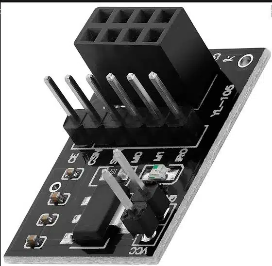
Solving Power Problems with Adapter Board
If you experience unreliable communication, random disconnections, or the module not responding at all, power supply issues are the likely cause. An adapter board provides voltage regulation, filtering capacitors, and easy connection to breadboards. This small investment saves hours of troubleshooting.
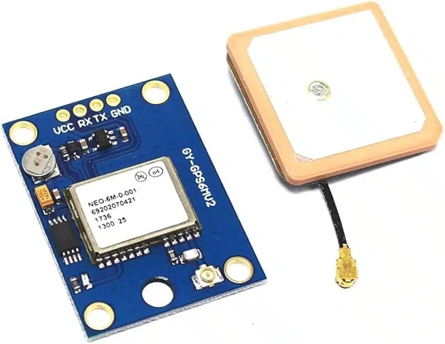
GPS Location Tracking with NEO-6M
The NEO-6M GPS module adds location awareness to your Arduino projects. By receiving signals from GPS satellites, it calculates precise coordinates (latitude and longitude), altitude, speed, and time. This opens possibilities for vehicle tracking, navigation systems, geocaching devices, and location-based automation.
How GPS Works
GPS satellites continuously broadcast their position and the current time. Your GPS module receives these signals from multiple satellites (at least four for accurate positioning) and calculates its location through trilateration. The module then sends this data to your Arduino through serial communication in a format called NMEA sentences.
The raw NMEA data contains all the information but in a format that requires parsing. Libraries like TinyGPS++ handle this parsing automatically, giving you easy access to latitude, longitude, altitude, speed, date, and time values.
Vehicle and asset tracking systems. Pet and child location trackers. Drone flight logging. Geotagging for photography projects. Speed and distance measurement. Time synchronization for data logging. Geofencing alerts when objects leave designated areas.
First-Time Setup
GPS modules need clear sky view to receive satellite signals. Indoor testing rarely works unless you place the antenna near a window. On first use, the module performs a "cold start" which can take several minutes to acquire satellites. Subsequent startups are faster because the module remembers satellite positions in its battery-backed memory.
#include <TinyGPS++.h>
#include <SoftwareSerial.h>
TinyGPSPlus gps;
SoftwareSerial gpsSerial(4, 3); // RX, TX
void setup() {
Serial.begin(9600);
gpsSerial.begin(9600);
}
void loop() {
while (gpsSerial.available() > 0) {
gps.encode(gpsSerial.read());
if (gps.location.isUpdated()) {
Serial.print("Lat: ");
Serial.println(gps.location.lat(), 6);
Serial.print("Lng: ");
Serial.println(gps.location.lng(), 6);
}
}
}
If you see no data, verify wiring (TX from GPS connects to RX on Arduino). If you see NMEA sentences but no valid coordinates, the module needs clearer sky view. The LED on the module blinks once per second when it has a position fix. First acquisition can take 1 to 12 minutes depending on conditions, so be patient during initial testing.
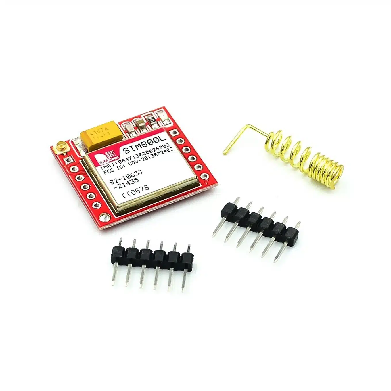
Cellular Communication with SIM800L
When your project needs to communicate from locations without WiFi or where the range of Bluetooth and RF modules falls short, cellular communication provides the answer. The SIM800L GSM module enables your Arduino to send SMS messages, make phone calls, and even connect to the internet through GPRS, anywhere with mobile network coverage.
Understanding GSM Communication
The SIM800L connects to cellular networks just like a mobile phone. Insert a SIM card (2G network compatible), and your Arduino can send text messages to any phone number, make voice calls, or transmit data over GPRS. Communication with the module happens through AT commands sent over serial connection.
This technology excels in remote monitoring applications. A weather station in a field can SMS daily reports. A security system can call you when triggered. A vehicle tracker can send its GPS coordinates via text message regardless of WiFi availability.
SMS-based alert systems for security or environmental monitoring. Remote control of devices via text message commands. Vehicle tracking with GPS coordinates sent via SMS. Agricultural monitoring in remote locations. Emergency notification systems. IoT data logging to cloud servers via GPRS.
The SIM800L requires 3.7V to 4.2V power supply capable of delivering 2A peak current during transmission bursts. The Arduino 3.3V or 5V pins cannot provide this. Use a dedicated LiPo battery (3.7V) or a buck converter set to 4V. Inadequate power causes random resets, failed connections, and unreliable operation. This is the most common source of SIM800L problems.
AT Commands Basics
The SIM800L responds to AT commands. Send "AT" to check if the module responds (it replies "OK"). Send "AT+CSQ" to check signal quality. Send "AT+CMGF=1" to set SMS text mode. Each command follows a predictable pattern, and the module confirms successful commands with "OK" responses.
#include <SoftwareSerial.h>
SoftwareSerial gsmSerial(7, 8); // RX, TX
void setup() {
gsmSerial.begin(9600);
delay(3000); // Wait for module to initialize
gsmSerial.println("AT+CMGF=1"); // Text mode
delay(1000);
gsmSerial.println("AT+CMGS=\"+92300XXXXXXX\"");
delay(1000);
gsmSerial.print("Hello from Arduino!");
gsmSerial.write(26); // Ctrl+Z to send
}
void loop() { }
The SIM800L LED tells you the network status. Blinking every 1 second means the module is searching for a network. Blinking every 2 seconds indicates GPRS data connection is active. Blinking every 3 seconds means the module has registered with the cellular network and is ready for SMS and calls. No blinking usually indicates power problems.
Choosing the Right Module: Decision Guide
With multiple wireless options available, selecting the right module depends on answering a few key questions about your project requirements.
Choose Bluetooth (HC-05) When:
You want to control your project from a smartphone. The communication distance is within 10 meters. You need a simple, beginner-friendly solution. Your project involves a single Arduino and a phone/computer. You want to build custom apps using MIT App Inventor or similar tools.
Choose RF (NRF24L01) When:
Two or more Arduinos need to communicate with each other. Phone control is not required. You need longer range than Bluetooth (up to 100+ meters). Battery life is important (very low power consumption). You want to create mesh networks with multiple nodes. Cost per node matters (NRF24L01 modules are inexpensive).
Choose GPS (NEO-6M) When:
Your project needs to know its physical location. You are building a tracker for vehicles, assets, or people. Navigation or mapping features are required. You need accurate time synchronization. The device will be used outdoors with sky visibility.
Choose GSM (SIM800L) When:
The project operates in remote locations without WiFi. You need to send alerts via SMS to any phone. Communication range must be unlimited (anywhere with cell coverage). Internet connectivity through GPRS is acceptable. You are willing to manage SIM card and credit. Power supply can meet the module's requirements.
Many advanced projects combine multiple wireless technologies. A vehicle tracker might use NEO-6M GPS to get coordinates and SIM800L to send those coordinates via SMS. A home automation system might use NRF24L01 for sensor nodes throughout the house with one central Arduino that has HC-05 for smartphone control. Think about your project's complete requirements before committing to a single technology.
Common Mistakes to Avoid
Working with wireless modules introduces challenges that pure wired projects do not face. Learning from common mistakes saves considerable time and frustration.
Inadequate power supply. Both NRF24L01 and SIM800L are sensitive to power quality. The Arduino 3.3V pin often cannot supply enough current for reliable operation. Use dedicated regulators or batteries appropriate for each module.
Ignoring voltage levels. HC-05 and NRF24L01 use 3.3V logic. While some pins are 5V tolerant, connecting 5V directly to 3.3V input pins risks damage. Use voltage dividers or level shifters when necessary.
Testing GPS indoors. GPS modules need clear sky view. Testing indoors typically results in no satellite fix. Move to a location with open sky access, such as near a window or outdoors.
Forgetting antenna connections. RF performance depends heavily on antenna quality and connection. Ensure antennas are properly attached. For NRF24L01, even the small PCB antenna must remain unobstructed.
Using wrong libraries. Each module has preferred libraries that handle low-level communication. Using outdated or incorrect libraries causes mysterious failures. Verify library compatibility with your specific module version.
Getting Started Checklist
Before beginning your wireless project, ensure you have everything needed for success:
Verify power supply meets module requirements. Check voltage levels match between Arduino and module. Download and install appropriate libraries. Have test code ready to verify basic functionality. Keep module documentation accessible for reference.
Start with the simplest test possible. For Bluetooth, send a single character and check if it arrives. For NRF24L01, transmit a known message and verify reception. For GPS, display raw NMEA sentences before parsing. For GSM, test AT command responses before attempting SMS. Building complexity gradually helps identify problems early.
Browse All Wireless Communication Modules at ColGroadReady to Make Your Project Wireless?
Order your wireless modules directly from our website with delivery across Pakistan. Need help choosing the right module for your specific project?
WhatsApp: 0323 0235000