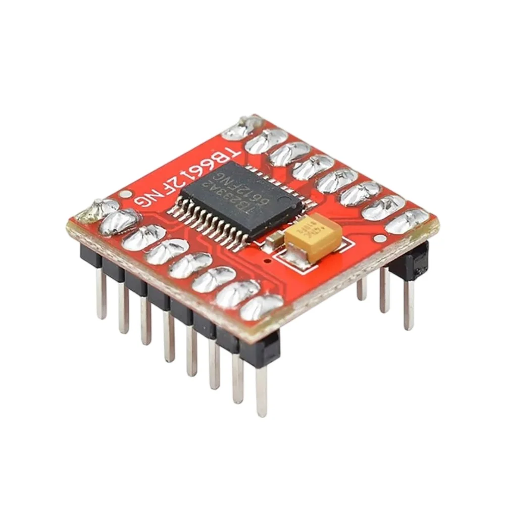
TB6612FNG Dual Stepper Motor Driver Module Overview
The TB6612FNG motor driver is a compact, efficient dual H-bridge breakout designed for precise control of DC and bipolar stepper motors. Ideal for Arduino and Raspberry Pi projects, robotics, CNC prototyping, and DIY automation, this module provides stable motor control with low heat output and built-in safety features.
Key Benefits
- Drive two independent DC motors or one bipolar stepper motor using both H-bridges
- Low standby current and on-chip thermal shutdown for reliable long-term operation
- Wide operating voltage: 2.5V to 13.5V, suitable for a variety of motor types
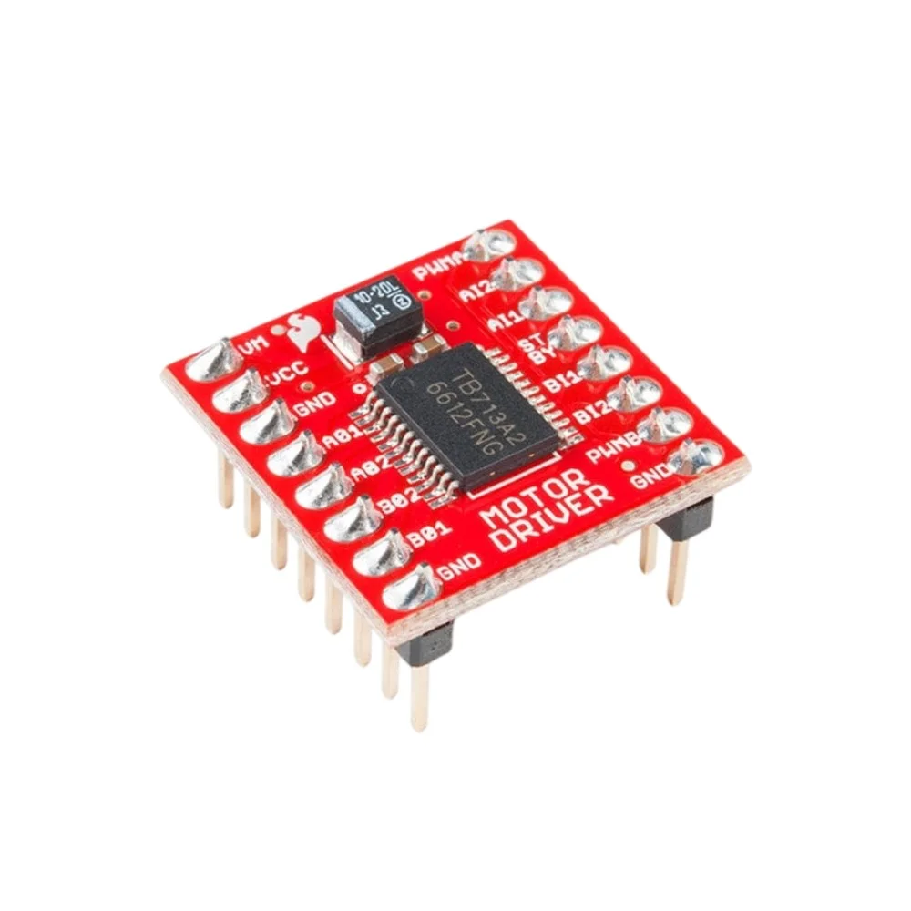
- Compact breakout board with clearly labeled TB6612FNG pinout for fast wiring
- Great balance of power and efficiency for battery-powered and bench projects
Technical Specifications
- Chip: TB6612FNG dual H-bridge motor driver
- Operating voltage: 2.5V to 13.5V (VM motor supply)
- Logic supply (VCC): 2.7V to 5.5V (check your microcontroller voltage)
- Peak output current: 3.2A per channel (single pulse)
- Recommended continuous current: follow motor and cooling specifications
- Protections: thermal shutdown and current limiting behavior on the die
- Board connectors: AIN1, AIN2, BIN1, BIN2, PWMA, PWMB, STBY, VM, VCC, GND, motor outputs AO1/AO2 and BO1/BO2
Compatibility and Use Cases
- Arduino and compatible microcontrollers for robotics and motion control
- Raspberry Pi projects that require motor actuation via GPIO and PWM
- Educational projects, prototypes, small CNC axes, camera sliders, and mobile robots
Wiring Guide and Typical Connections
Basic wiring is straightforward. Keep logic and motor power supplies separate if they use different voltages.
- VM (motor power): Connect to motor supply (2.5V to 13.5V). Add a decoupling capacitor close to the board.
- VCC (logic power): Connect to 3.3V or 5V logic depending on your controller.
- GND: Common ground between controller and motor power.
- AIN1 / AIN2 and BIN1 / BIN2: Direction control inputs for motor A and B.
- PWMA / PWMB: PWM speed control inputs for motor A and B. Use microcontroller PWM pins for speed regulation.
- STBY: Pull HIGH to enable the driver. Pull LOW to disable and reduce standby current.
- Motor outputs: AO1/AO2 and BO1/BO2 connect to motor coils or motor terminals.
Stepper Motor Notes
To drive a bipolar stepper motor, use both H-bridges as separate phase drivers and sequence AIN1/AIN2 and BIN1/BIN2 with appropriate PWM for current control. The TB6612FNG is ideal for full-step and half-step driving, but it does not provide advanced current microstepping on its own. For fine microstepping, use an external stepper controller with current regulation.
Example Arduino Wiring (Summary)
- VCC to 5V on Arduino
- VM to motor battery or power supply (add decoupling capacitor)
- GND to Arduino GND
- PWMA to Arduino PWM pin (e.g., D5), AIN1/AIN2 to two digital pins for direction
- PWMB to another PWM pin, BIN1/BIN2 to digital pins for second motor
- STBY tied HIGH to enable or controlled by a digital pin
Why Choose the TB6612FNG Module
- Reliable, noise-reduced operation for smoother motor performance
- Clear pinout and breakout format make prototyping fast and error-free
- Versatile enough for hobbyists, students, and professional engineers
- Includes TB6612FNG datasheet and wiring guide to get you up and running quickly
From classroom robotics to custom automation, the TB6612FNG breakout board is a dependable motor control module that performs consistently across varied applications. Ready to bring your motors to life? Order now and get precise, efficient motor control with the TB6612FNG motor driver.
Note: Pictures are for illustration purposes only.


Abdullah Abid (verified owner) –
Nice Quality
Abdullah Abid –