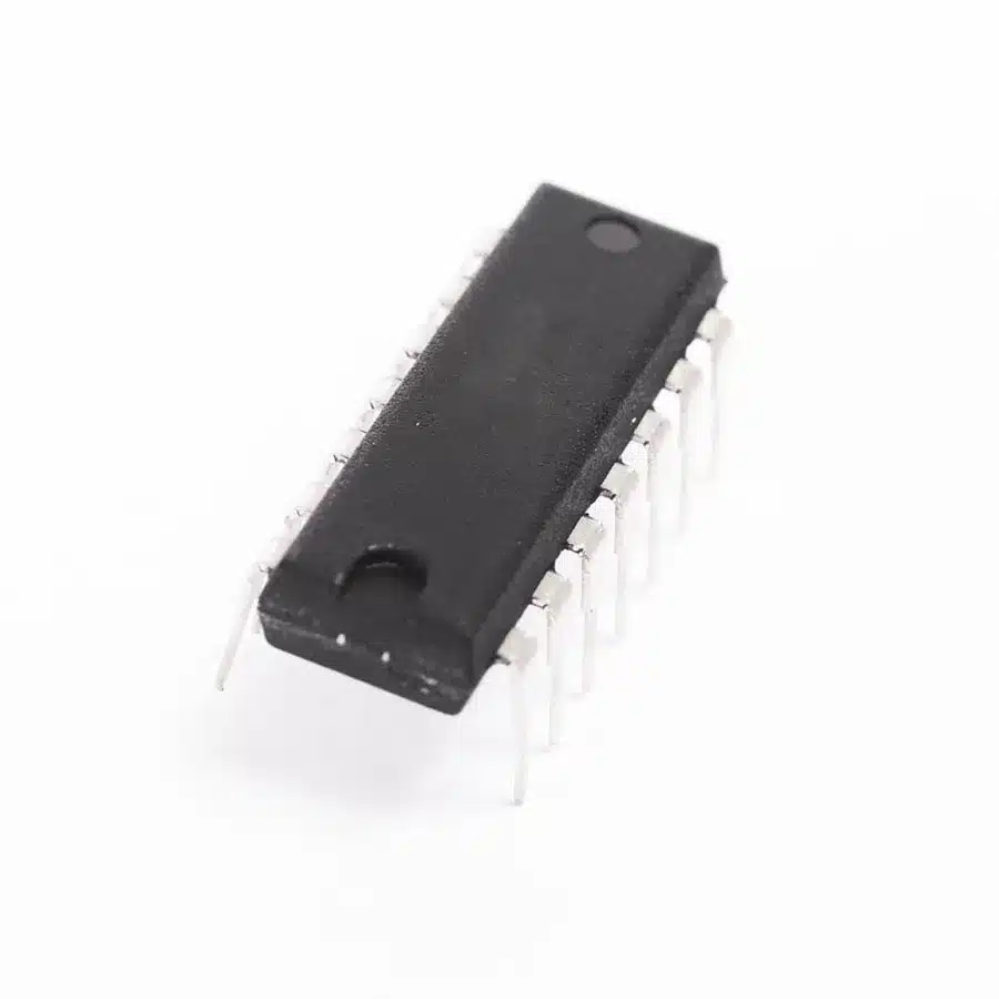
74386 Quad 2-Input XOR Gate IC (DIP) — Overview
The 74386 Quad 2-Input XOR Gate IC (DIP) integrates four independent 2-input Exclusive-OR gates in a single, easy-to-use package. Built on TTL logic technology, each XOR gate outputs HIGH when an odd number of inputs are HIGH. This IC is a core building block for arithmetic circuits, parity checking, and many general-purpose digital logic designs.
Key Features
- Four independent 2-input XOR gates in one DIP package
- Standard TTL logic compatibility (designed for 5V TTL systems)
- Breadboard- and prototyping-friendly Dual Inline Package
- Low power consumption and high noise immunity for stable operation
- Fast switching suitable for combinational and sequential logic
Technical Specifications
- Logic family: TTL-compatible
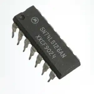
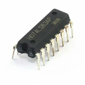
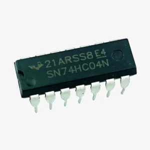
- Package type: 14-pin Dual Inline Package (DIP)
- Supply: standard TTL VCC (commonly 5V)
- Number of gates: 4 independent 2-input XORs
- Typical uses: adders, parity generation/checking, comparators, logic control
Truth Table
- A = 0, B = 0 → Y = 0
- A = 0, B = 1 → Y = 1
- A = 1, B = 0 → Y = 1
- A = 1, B = 1 → Y = 0
Applications
- Binary adders and arithmetic logic units (ALUs)
- Parity generators and error detection/correction circuits
- Data comparison and equality detection circuits
- General-purpose digital logic and educational lab projects
Package and Pin Information
The 74386 is supplied in a standard 14-pin DIP suitable for breadboards and through-hole PCBs. VCC and GND follow standard TTL pin positions in the DIP footprint. Always consult the manufacturer datasheet for exact pin mapping and electrical limits before PCB layout or final designs.
Why Choose the 74386 for Your Project
- Compact quad-gate solution reduces component count in logic designs
- TTL compatibility ensures easy integration with legacy and modern TTL-level systems
- Ideal for prototyping and classroom use due to DIP packaging
- Reliable performance for both hobby and professional digital electronics
Ordering and Notes
Suitable for students, hobbyists, and professionals working on logic circuit design. Note: images may be for illustration purposes only; refer to the specific manufacturer datasheet for detailed electrical characteristics and timing information.


Reviews
There are no reviews yet