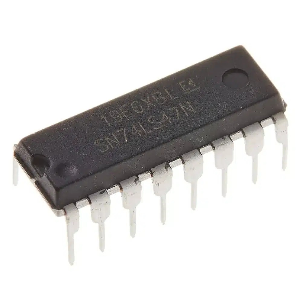
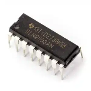
Overview: 7447 BCD to 7-Segment Decoder/Driver IC (DIP)
The 7447 BCD to 7-Segment Decoder/Driver converts a 4-bit binary coded decimal input into the seven-segment signals needed to display digits 0 to 9 on common-anode LED displays. With open-collector, active-LOW outputs and TTL-compatible inputs, the 7447 simplifies numeric display designs in counters, clocks, meters, microcontroller projects, and educational kits.
Key Features
- BCD (A, B, C, D) to seven-segment decode for digits 0 to 9
- Common-anode display driver with open-collector, active-LOW outputs (a–g)
- Control pins: LT (Lamp Test), BI̅ (Blanking Input), RBI and RBO for cascading and blanking
- TTL-compatible inputs; nominal 5 V supply for rapid switching
- Standard DIP-16 package, compatible with breadboards and through-hole PCBs
Technical Specifications
- Supply voltage: 4.75 to 5.25 V (TTL)
- Inputs: A, B, C, D (BCD), LT, BI̅, RBI
- Outputs: a, b, c, d, e, f, g (active-LOW), plus RBO
- Display type: Common-anode 7-segment
- Package: DIP-16
Control Pins and Functions
- LT (Lamp Test): Forces all segment outputs LOW to illuminate every segment for testing.
- BI̅ (Blanking Input): When asserted, blanks the display by turning off all segments.
- RBI (Ripple Blanking In) and RBO (Ripple Blanking Out): Support leading-zero suppression when cascading multiple digits. Use RBI from the next digit to propagate blanking signals.
Wiring and Usage Tips
- Connect the display common anode to +5 V.
- Place a current-limiting resistor in series with each segment between the segment pin and the 7447 output to limit LED current.
- Inputs A, B, C, D receive the BCD code. Drive them with TTL outputs or a microcontroller interface at 5 V logic levels.
- Use LT for quick lamp tests during manufacturing or debugging. Use BI̅ to blank the display for power saving or visual effects.
- For multi-digit displays, cascade RBO of the less significant digit to RBI of the next digit to implement ripple blanking and leading-zero suppression.
Typical Applications
- Up/down counters and frequency displays
- Digital clocks, timers, and stopwatches
- Microcontroller numeric readouts and training labs
- Educational kits, prototyping boards, and hobby electronics
Package and Prototyping
The DIP-16 package makes the 7447 ideal for breadboard prototyping and through-hole PCB designs. Its TTL-level inputs allow direct interfacing with legacy logic families and many microcontrollers when run at standard 5 V.
Usage tip: When wiring, remember the 7447 outputs are active-LOW open-collector. The common anode goes to +5 V and each segment line should include a resistor to limit LED current.
Note: Images are for illustration purposes only.


Anonymous (verified owner) –
all failed
Anonymous –